
Impedance is the total opposition to AC current in a circuit. It combines resistance and reactance into a single value in ohms. Calculating impedance and reactance correctly is essential for AC circuit design, motor sizing, cable selection, and power factor analysis.
This guide covers impedance and reactance with formulas, worked examples, and a live RLC impedance calculator.
Impedance Z = √(R² + (XL − XC)²). Inductive reactance increases with frequency. Capacitive reactance decreases with frequency. Resistance stays constant. All three combine in the impedance triangle.
Impedance and Reactance in AC Circuits: Key Concepts
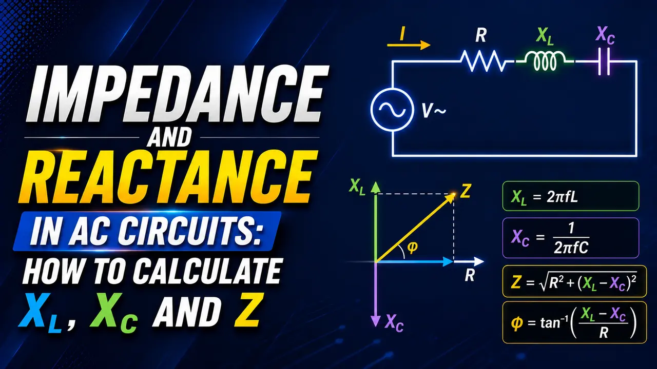
In a DC circuit, opposition to current is resistance (R) only. In an AC circuit, inductors and capacitors also oppose current -- but in a frequency dependent way. This additional opposition is called reactance (X).
The total opposition -- combining resistance and reactance -- is called impedance (Z), measured in ohms.
It has both a magnitude and a phase angle (φ) that describes whether the circuit is inductive, capacitive, or resistive.
Impedance and Reactance Formulas
Inductive Reactance (XL)
An inductor opposes changes in current. In AC circuits, it creates an opposition that grows as frequency increases. A 50 Hz inductor has lower reactance than the same inductor at 1,000 Hz.
f: frequency (Hz)
L: inductance (henries, H)
Example: L = 0.1 H at f = 50 Hz → XL = 2π × 50 × 0.1 = 31.4 Ω
Inductive reactance appears in motor windings, transformer primary coils, and inductors in filter circuits. See the reactance guide for more on how XL behaves across the frequency range.
Capacitive Reactance (XC)
A capacitor opposes changes in voltage. Its reactance decreases as frequency increases -- the opposite of an inductor. At DC (zero frequency), a capacitor is an open circuit. At very high frequency, it approaches a short circuit.
f: frequency (Hz)
C: capacitance (farads, F)
Example: C = 100 µF at f = 50 Hz → XC = 1 / (2π × 50 × 0.0001) = 31.8 Ω
Capacitive reactance is important in power factor correction capacitor banks, cable capacitance calculations, and RC filter design. See the capacitor types guide for how capacitance values vary by technology.
Total Impedance in a Series RLC Circuit
When a resistor, inductor, and capacitor are in series, their individual effects combine into a single impedance value. The resistive and reactive parts cannot simply be added -- they combine using the Pythagorean theorem because they are 90° out of phase with each other.
R: resistance (ohms)
XL: inductive reactance (ohms)
XC: capacitive reactance (ohms)
Phase angle φ: arctan((XL − XC) / R)
If XL > XC: circuit is inductive (voltage leads current)
If XC > XL: circuit is capacitive (current leads voltage)
If XL = XC: resonance, Z = R only (minimum impedance)
Worked Impedance and Reactance Calculation Example
A series RLC circuit has R = 30 Ω, L = 0.2 H, C = 50 µF, connected to a 230 V, 50 Hz supply.
Step 2: XC = 1 / (2π × 50 × 0.00005) = 63.66 Ω
Step 3: Net reactance X = XL − XC = 62.83 − 63.66 = minus 0.83 Ω (slightly capacitive)
Step 4: Z = √(30² + (minus 0.83)²) = √(900 + 0.69) = 30.01 Ω
Step 5: φ = arctan(minus 0.83 / 30) = minus 1.6° (nearly unity power factor)
Step 6: Current I = V / Z = 230 / 30.01 = 7.66 A
Note: this circuit is near resonance (XL ≈ XC). Current is high and power factor is nearly 1.0.
Series RLC Impedance and Reactance Calculator
Impedance and Reactance: Full Comparison Table
| Property | Resistance (R) | Inductive Reactance (XL) | Capacitive Reactance (XC) | Impedance (Z) |
|---|---|---|---|---|
| Symbol | R | XL | XC | Z |
| Unit | Ohms (Ω) | Ohms (Ω) | Ohms (Ω) | Ohms (Ω) |
| Formula | V/I (DC or AC) | 2πfL | 1/(2πfC) | √(R² + (XL−XC)²) |
| Frequency effect | None (constant) | Increases with f | Decreases with f | Depends on all three |
| Phase effect | Voltage in phase with current | Voltage leads current by 90° | Current leads voltage by 90° | Between 0° and 90° |
| Dissipates power? | Yes (heat) | No | No | Only R component dissipates |
Where Impedance and Reactance Calculations Apply in Practice
Power Factor Correction
Capacitors are added to cancel inductive reactance from motor loads. The capacitor XC must equal the XL of the load at the supply frequency for unity power factor. See the power factor correction guide.
Motor and Transformer Analysis
Motor windings have both resistance and inductive reactance. The total impedance determines starting current, running current, and power factor. At starting, XL is low (the rotor is stationary and slip is 1) -- current surges. See the reactive power guide.
Short Circuit Current Calculation
Impedance of cables, transformers, and busbars limits fault current. The prospective short circuit current at any point equals the source voltage divided by the total impedance of the fault path. See the short circuit calculation guide.
Instrument Loop Impedance
4 to 20 mA instrument loops have maximum loop impedance constraints. Cable resistance and barrier impedance both contribute to the total loop impedance that the transmitter must drive. See the instrument loop impedance guide.
Watch: AC Circuits -- Impedance, Reactance and Resonant Frequency
Impedance and Reactance Questions
External References
- Impedance and Admittance -- All About Circuits (AC Theory Chapter 5)
- AC Resistance and Impedance -- Electronics Tutorials
What We Learn Today
- Impedance Z = √(R² + (XL − XC)²) -- the total opposition to AC current combining resistance and reactance
- Inductive reactance XL = 2πfL -- increases with frequency; voltage leads current by 90°
- Capacitive reactance XC = 1/(2πfC) -- decreases with frequency; current leads voltage by 90°
- At resonance (XL = XC), reactances cancel, Z = R, phase angle = 0°, and power factor = 1.0
- Phase angle φ = arctan((XL − XC) / R) -- positive means inductive, negative means capacitive
- Only resistance dissipates real power -- reactance stores and returns energy without dissipation