
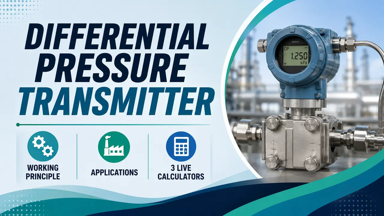
A differential pressure transmitter measures the difference between pressure at two points and converts it to a 4 to 20 mA or digital output. A single instrument covers flow measurement, level measurement, and density measurement depending only on how the impulse lines are connected.
This guide covers the working principle, the three main measurement applications, and interactive calculators for DP flow, DP level span, and square root extraction.
The differential pressure (DP) transmitter is the most versatile instrument in process measurement. The same body measures flow, level, density, or filter pressure loss.
The measurement application changes purely by changing which two process points the HP and LP ports are connected to.
How a Differential Pressure Transmitter Works
The transmitter body contains a sensing diaphragm separating the high pressure (HP) and low pressure (LP) chambers.
Process fluid acts on both sides through the impulse lines. The diaphragm deflects in proportion to the pressure difference between the two sides.
The deflection is converted to an electrical signal by a capacitance, piezoelectric, or strain gauge sensor element.
A signal conditioning circuit converts this to a 4 to 20 mA analog output or a digital HART/Fieldbus signal proportional to the measured differential pressure.
The zero of the output (4 mA) corresponds to zero differential pressure, and the full scale output (20 mA) corresponds to the calibrated upper range value (URV). For more detail on the DP transmitter basics, refer to the companion article.
3 Main Applications -- Select One to Explore
The same transmitter hardware covers three completely different process measurements. The application depends only on how the HP and LP impulse lines are connected to the process.
A primary element such as an orifice plate, venturi tube, or flow nozzle creates a pressure drop proportional to the square of the fluid velocity. The HP port connects upstream of the restriction, the LP port connects downstream.
The flow rate is proportional to the square root of the measured differential pressure. Doubling the flow rate quadruples the DP reading.
The transmitter or the control system must apply square root extraction to convert DP to a linear flow signal.
For level measurement, the HP port connects to the vessel bottom and the LP port connects to the top vapour space or sealed reference leg.
The DP reading equals the hydrostatic pressure of the liquid column above the HP tapping.
The transmitter span is calculated from the liquid density, gravity, and the distance between the HP tapping and the maximum level.
Zero suppression or zero elevation is applied when the transmitter is mounted above or below the HP tapping. Refer to the zero elevation and suppression guide for the mounting correction procedure.
A DP transmitter across a filter or heat exchanger measures pressure loss, which increases as the filter loads with solids or as scaling builds up on heat exchanger tubes. A rising DP indicates it is time to clean or replace the element.
For density measurement, the HP port connects to the bottom of a vertical pipe section of known height H and the LP port to the top.
The DP equals ρ × g × H, so density is calculated as DP / (g × H).
The Square Root Relationship: Why It Matters for DP Flow
The relationship between differential pressure and flow rate is quadratic -- not linear. The chart below shows how the DP reading and actual flow relate across the operating range. At 50% DP, the flow is only 70.7% of full scale -- not 50%.
3 Interactive DP Transmitter Calculators
Installation and Impulse Line Rules
The impulse lines connecting the process to the transmitter are one of the most important factors in measurement accuracy. Errors in impulse line installation cause more DP measurement problems than transmitter faults.
| Requirement | Liquid Service | Gas Service | Steam Service |
|---|---|---|---|
| Transmitter position | Below the tappings so liquid fills the impulse lines naturally | Above the tappings so gas fills the lines and any condensate drains back | Condensate pots at the tapping level; transmitter below |
| Slope of impulse lines | Continuous downward slope from tapping to transmitter -- no pockets where gas can trap. See impulse line slope guide. | Continuous upward slope from tapping to transmitter -- no pockets where liquid can trap | Both lines to condensate pots must slope continuously to the pot |
| Effect of a trapped gas bubble (liquid service) | A gas bubble in the HP line causes a low reading. A bubble in the LP line causes a high reading. | Not applicable -- gas fills the lines by design | Unequal condensate levels in the two legs cause a constant zero offset |
| Equalising valve | Required for zero check -- opens both sides to the same pressure so transmitter should read zero | Same | Same -- but must cool lines before equalising on steam |
| Isolation and drain valves | Isolation valve each side; drain/vent to confirm fluid type before opening | Isolation valve each side; vent to confirm gas before opening | Isolation, drain, and condensate pot drain valves per standard five valve manifold |
Watch: DP Transmitter Working Principle with Animation
Differential Pressure Transmitter Questions
External References
- Rosemount 3051 DP Transmitter Product Data Sheet -- Emerson
- DP Transmitter Selection Guide -- Yokogawa
What We Learn Today
- A DP transmitter measures the difference between two pressures -- the application (flow, level, or density) is set by how the impulse lines are connected
- DP flow uses the square root relationship: flow is proportional to the square root of DP, not to DP directly
- DP level span = ρ × g × H_range -- always use actual process liquid density at operating temperature
- For liquid service, impulse lines must slope continuously downward with no gas pockets; for gas service, upward with no liquid pockets
- Square root extraction must be applied once only -- in the transmitter or the DCS, never both
- Zero shift and span drift are the two most common transmitter errors after installation -- verify with the equalising valve and a known reference