
A CTU counts up toward a target. A CTD counts down toward zero. Both instructions look almost identical on a rung, yet mixing up which one a machine actually needs is a common early mistake.
The accumulated value behind both instructions is retentive, holding its count across scans and even a power cycle, until something explicitly resets it.
Neither instruction counts continuously while its input stays on. Both only respond to a single rising edge per scan, a detail that trips up more than one first attempt at counter logic.
This guide walks through both instructions, their parameters, and a calculator that tracks the accumulated value through a real pulse sequence.
PLC counter instructions CTU and CTD track how many times an event has happened, CTU counting up from zero toward a preset value and CTD counting down from a preset value toward zero, each incrementing or decrementing its accumulated value by one on every rising edge of its input, with a done bit that turns on once the target is reached.
Almost every PLC program that needs to know how many times something happened, a part passing a sensor, a cycle completing, a batch filling, leans on a counter instruction rather than counting manually with math blocks.
CTU and CTD cover the two directions that counting can go, and a third instruction, CTUD, combines both directions on the same accumulated value.
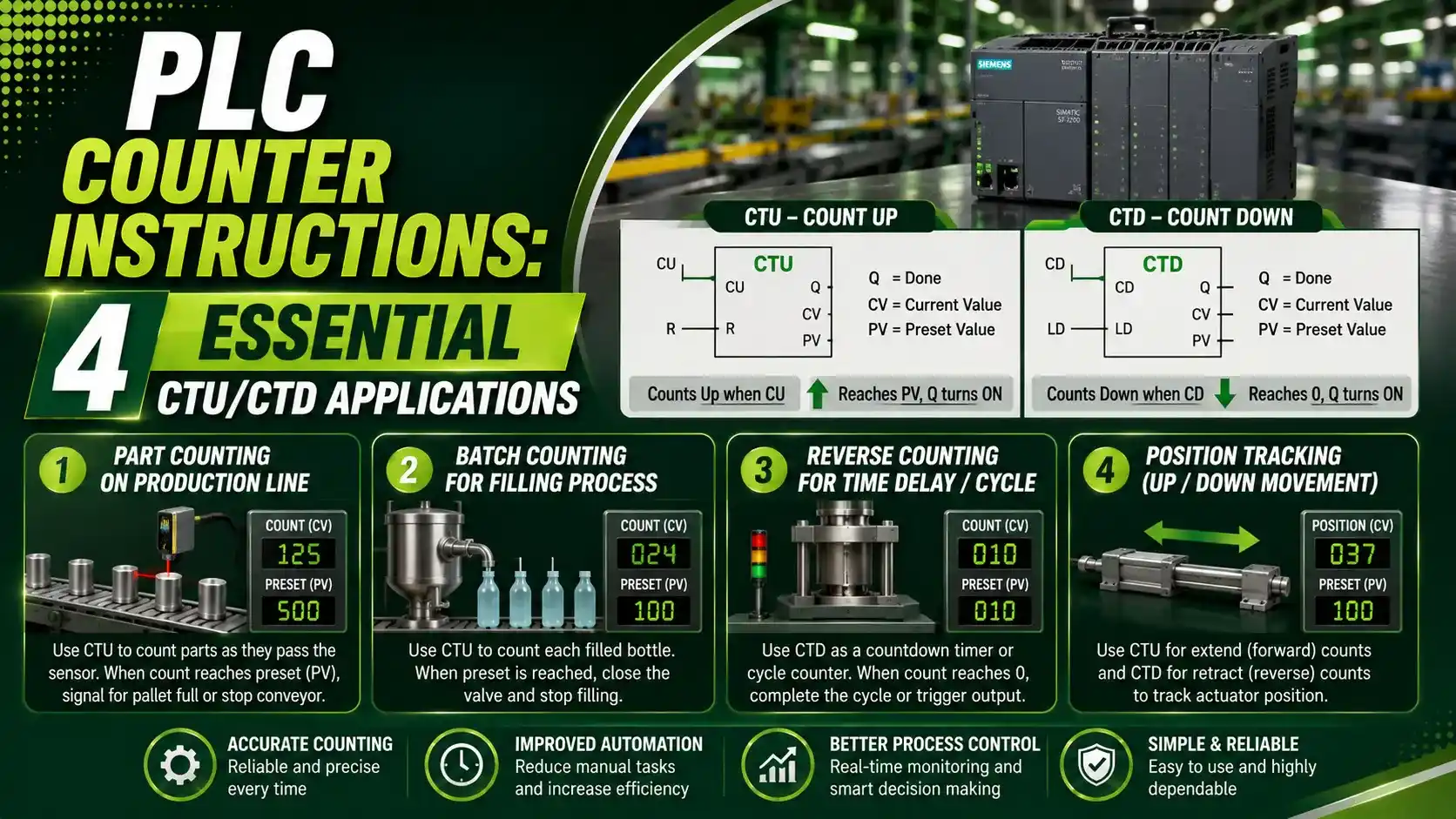
This article breaks down how each instruction behaves scan by scan, the parameters they share, and a calculator for tracking the accumulated value through a real pulse sequence.
How CTU, Count Up, Actually Works
A CTU instruction increases its accumulated value, ACC, by one every time its rung condition transitions from false to true, a single rising edge.
Once ACC reaches or exceeds the preset value, PRE, the done bit, DN, turns on and stays on even if the counter keeps counting past the preset.
ACC does not reset itself once the target is reached. It keeps climbing, and DN stays true, until a separate reset instruction clears it back to zero.
How CTD, Count Down, Actually Works
A CTD instruction decreases its accumulated value by one on every rising edge of its input, the mirror opposite of CTU.
CTD is usually loaded with a starting value equal to the preset, then counts down from there. The done bit turns on once ACC reaches zero or below.
Unlike some simpler counting schemes, a CTD does not stop at zero on its own. Left uncontrolled, it can keep counting into negative numbers, which is exactly what the underflow bit exists to flag.
CTUD: Combining Both Directions in One Instruction
CTUD wires a count up input, CU, and a count down input, CD, to the same accumulated value, so one instruction can both add and subtract from the same running total.
Two separate done bits track the two directions. QU turns on once ACC reaches or exceeds the preset, and QD turns on once ACC reaches zero or below.
A warehouse buffer tracking parts arriving and parts leaving is the classic use case, one CTUD tag instead of two separate counters that would otherwise need to be manually kept in sync.
Counter Instruction Parameters Compared
| Parameter | Full Name | What It Does |
|---|---|---|
| PRE / PV | Preset Value | The target count the instruction works toward |
| ACC / CV | Accumulated Value | The running count, retained across scans and power cycles |
| DN / Q | Done Bit | Turns on once ACC crosses the preset in the counting direction |
| RES | Reset Instruction | Clears ACC back to zero when its rung condition is true |
CTU / CTD Accumulated Value Simulator
Pick a counter type, set a preset value, and enter how many rising edge pulses have occurred, to see the resulting accumulated value and done bit state.
Two Counter Scenarios Worked Through
A CTU with a preset of 100 that has received 65 pulses is still short of its target, ACC sits at 65 and the done bit stays off until 35 more pulses arrive.
ACC = 65
Done Bit = OFF
A CTD with a preset of 50 that has received 60 pulses has run straight past zero, ACC lands at negative 10 and the done bit turns on, since it already crossed zero ten pulses earlier.
ACC = minus 10
Done Bit = ON
Four Real Counter Instruction Applications
Conveyor Part Counting
A CTU counts bottles or boxes passing a photo eye, stopping the line once a batch preset is reached.
Maintenance Cycle Tracking
A CTU counts press or valve cycles, triggering a maintenance alert once a service interval preset is hit.
Warehouse Buffer Level
A CTUD tracks parts entering and leaving a buffer on one shared value, always reflecting the current count.
Batch Countdown
A CTD counts down remaining units in a batch, signaling done once the last unit has been processed.
PLC Counter Instruction Do's and Don'ts
✓ Do
- Pair every counter with an explicit RES instruction, ACC never resets itself
- Use CTUD instead of separate CTU and CTD tags when tracking one running total in both directions
- Check the overflow and underflow bits on any counter that could realistically hit its numeric limit
- Remember ACC is retentive, plan for what a leftover value means after a power cycle or restart
✗ Don't
- Expect a counter to increment continuously while its input stays true, only a rising edge counts
- Assume CTD stops at zero on its own, it will keep going negative without a control interlock
- Forget to reset ACC before a counter is reused for a new batch or cycle
- Confuse the done bit's latching behavior, it stays on past the preset until reset, not just momentarily
Resources on PLC Counter Instructions
PLC Counter Instructions Questions Engineers Ask
External References
- Control System Guide: PLC Counter Explained, CTU, CTD, CTUD Plus Examples
- RealPars: PLC Counters Explained in Studio 5000 Logix Designer
What We Learn Today
- CTU counts up toward a preset, CTD counts down toward zero, and CTUD combines both on one accumulated value.
- Every counter only responds to a rising edge on its input, never a continuously true condition.
- The accumulated value is retentive and does not reset itself, an explicit RES instruction is required.
- A CTD left unchecked can run past zero into negative numbers, which the underflow bit is built to flag.