
Every instruction a processor executes eventually lands on the same small block of combinational logic.
Understanding how that block adds, compares, and branches is the fastest way to understand how a CPU actually thinks.
An Arithmetic Logic Unit (ALU) is the combinational digital circuit inside a processor that performs arithmetic operations like addition and subtraction, and logical operations like AND, OR, and XOR, selecting the correct result through a control signal and reporting status flags such as carry, zero, and overflow.
Every calculation a computer performs, whether it's adding two numbers in a spreadsheet or comparing two values in an if-statement, eventually passes through an ALU.
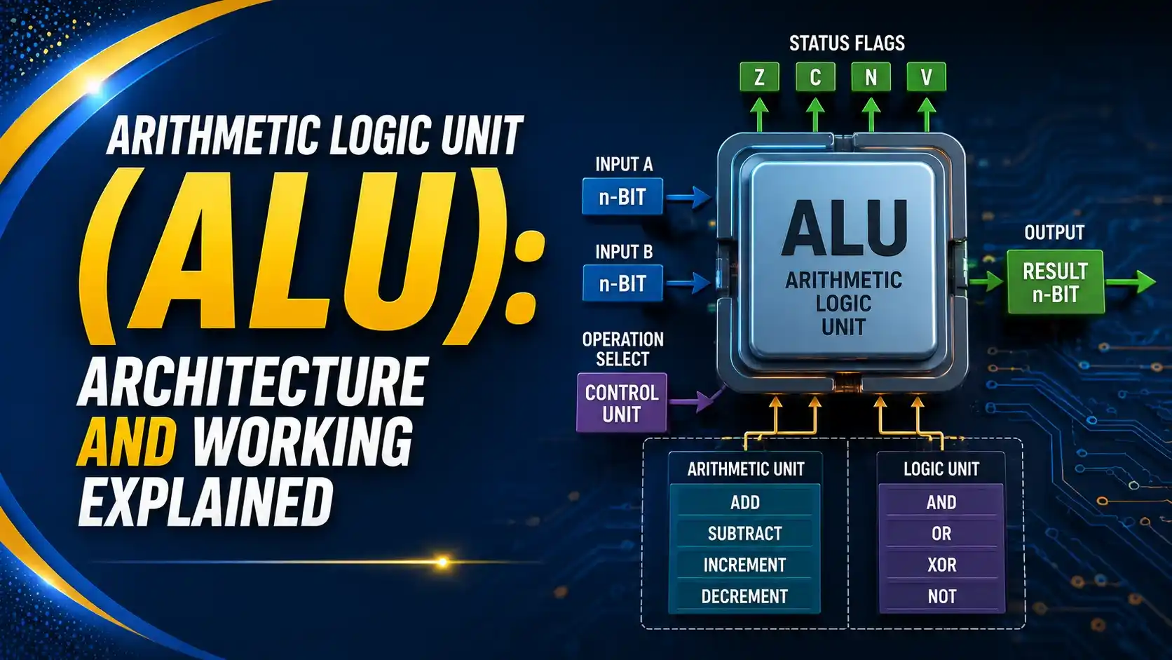
It's easy to think of the CPU as one intelligent black box, but the actual "thinking" happens in a tiny, fixed piece of hardware that has no memory of its own and no concept of a program. It receives two binary inputs and a control code, and within a fraction of a nanosecond, it produces an output and a set of flags.
That simplicity is deliberate. An ALU built from a handful of logic gates can run at gigahertz speeds precisely because it does one narrow job extremely well, rather than trying to be clever.
Modern high-performance cores don't rely on a single ALU either. A processor like the ARM Cortex-X4 packs multiple integer execution units so several instructions can be evaluated in the same clock cycle, which is one of the main levers behind modern single-core performance gains.
This guide breaks down what's actually inside an ALU, how it decides which operation to run, how it reports its status through flags, and where this decades-old design shows up in the processors running today.
What an ALU Actually Does
At its simplest, an ALU is a black box with two n-bit data inputs, a control input that selects the operation, and two outputs: the result and a set of status flags describing that result.
Internally it's built entirely from combinational logic, meaning it has no clock and no memory of previous operations. Feed it the same three inputs twice and it produces the exact same output both times, with no dependency on history.
This is what separates the ALU from the rest of the CPU. The control unit, registers, and program counter all involve sequential logic and state. The ALU is pure computation, wired once in silicon and reused for every arithmetic or logical instruction the processor ever executes.
Inside the ALU: The Two Functional Halves
Every general-purpose ALU is really two separate circuits sharing the same inputs, with a multiplexer picking which one's output actually reaches the pins.
Both the arithmetic and logic paths compute their results in parallel on every cycle, whether or not their output gets used. The multiplexer doesn't save power by skipping work; it just decides which of the two already-computed answers gets passed downstream.
How the Adder Actually Adds
The arithmetic path is built from a chain of full adders, and this is where most of an ALU's internal complexity lives.
A single full adder takes two bits plus a carry-in and produces a sum bit and a carry-out. Chain four of these together and each carry-out feeds the next stage's carry-in, which is enough to add two 4-bit numbers.
The problem is that this "ripple carry" design is slow at wide bit widths, because the final bit can't settle until the carry has rippled through every stage before it. A 64-bit ripple carry adder would be far too slow for a modern clock speed.
Real processors instead use a carry-lookahead adder, which calculates all the carry bits in parallel using extra logic upfront, trading additional gates for a dramatic reduction in propagation delay. Subtraction reuses the same adder hardware by inverting the second operand and injecting a carry-in of 1, which is two's complement subtraction happening in real time.
Try It: ALU Operation Simulator
The calculator below mirrors what the ALU's select lines and multiplexer do internally. Pick two operands and an operation to see the binary result and which status flags it sets.
The Core Operations an ALU Supports
Instruction sets vary, but almost every ALU exposes some version of the same core operation set, selected by a binary opcode on its control lines.
Arithmetic operations (ADD, SUB, and often increment or decrement) run through the adder chain. Logic operations (AND, OR, XOR, NOT) run through a bank of parallel gates, one per bit. Shift operations reposition bits within the register, which is functionally equivalent to fast multiplication or division by powers of two.
The select code, usually 3 to 6 bits wide depending on how many operations the ALU supports, feeds a decoder that activates the correct multiplexer path, exactly as demonstrated in the simulator above.
Status Flags: The ALU's Report Card
An ALU doesn't just hand back a number. It also reports metadata about that result through a small set of flag bits, and those flags are what let a CPU make decisions.
Carry (C)
Set when an addition produces a carry-out of the most significant bit, or a subtraction requires a borrow.
Zero (Z)
Set when the result equals zero, the flag nearly every conditional branch instruction checks first.
Sign (S)
Mirrors the most significant bit of the result, indicating a negative value in two's complement form.
Overflow (V)
Set when a signed operation produces a result too large or too small to fit in the available bits.
These flags are usually stored in a dedicated status register, and the control unit reads them immediately after every arithmetic or logic instruction. A "jump if zero" instruction, for example, is really just a check on the Z flag left behind by whatever operation ran before it.
Where ALUs Actually Live in Modern CPUs
Textbook diagrams show one ALU per processor, but that stopped matching reality decades ago.
| Processor Generation | Integer Execution Units | Design Implication |
|---|---|---|
| Classic single-issue CPUs | 1 ALU | One integer operation completes per cycle at most |
| Early superscalar cores | 2 to 3 ALUs | Multiple simple instructions can issue in parallel |
| ARM Cortex-X4 (2023) | Widened integer execution resources | One of the widest out-of-order ARM cores to date, per WikiChip's architecture analysis |
| High-end desktop and server cores | 4+ ALUs per core | Multiple independent integer pipelines feed from a shared instruction window |
Having multiple ALUs per core is what allows a superscalar processor to execute several independent integer instructions in the same clock cycle, provided the instruction scheduler can find operations without data dependencies to run together. The ALU itself hasn't gotten conceptually more complex. There are simply more of them, wired to a smarter dispatcher.
A Short History: From the 74181 to the Modern Core
Texas Instruments releases the 74181, the first complete ALU on a single TTL chip, supporting 32 arithmetic and logic functions on 4-bit operands.
Minicomputers and early microprocessors chain multiple 74181 chips together to build wider word sizes, a design documented extensively by hardware historians reverse-engineering the original die.
The ALU moves fully on-die as part of the integer execution unit, with carry-lookahead and carry-select adders replacing simple ripple carry for speed.
Modern cores run several ALUs per core in parallel, feeding out-of-order execution engines that keep each unit busy across overlapping instructions.
The 74181 is strange by modern standards, its logic doesn't map cleanly onto simple Boolean identities, and reverse-engineering its die surprised even experienced hardware historians. But its basic contract, two operands and a select code in, a result and flags out, is identical to what runs inside a processor today.
Where ALU Design Choices Matter Most
✓ Do
- Use carry-lookahead or carry-select adders for wide bit widths where ripple carry delay becomes a bottleneck
- Keep the logic unit's gates fully parallel so bitwise operations complete in a single gate delay
- Route status flags to a dedicated register the control unit can read immediately after execution
- Add multiple ALUs per core when the instruction scheduler can reliably find independent operations to pair
✗ Don't
- Assume a ripple carry adder scales acceptably past small bit widths
- Confuse the overflow flag with the carry flag, they track signed and unsigned edge cases differently
- Treat the ALU as sequential logic, it has no internal state or memory of prior operations
- Add extra ALUs without a scheduler capable of actually keeping them fed with independent work
Reference Materials on ALU Design
FAQs on Arithmetic Logic Unit (ALU)
External References
- Inside the Vintage 74181 ALU Chip: How It Works and Why It's So Strange, Ken Shirriff
- 74181, Wikipedia
- Lookahead Carry Unit, Wikipedia
- ARM Cortex-X4, Wikipedia
- Arm Introduces The Cortex-X4, Its Newest Flagship Performance Core, WikiChip Fuse
What we learn today
- An ALU is a purely combinational circuit with no internal memory, producing a result and status flags from two operands and a control code.
- Internally it splits into an arithmetic path built from adders and a logic path built from parallel Boolean gates, with a multiplexer selecting the active output.
- Wide adders use carry-lookahead logic instead of ripple carry to avoid unacceptable propagation delay at gigahertz clock speeds.
- The Carry, Zero, Sign, and Overflow flags are what let a CPU's control unit make branching decisions after every arithmetic or logic instruction.
- Modern superscalar cores run multiple ALUs per core in parallel, tracing back to Texas Instruments' 74181, the first single-chip ALU from 1970.