
A common mode choke does something that sounds almost like a magic trick. It blocks noise on two wires while letting the real signal pass through both of them untouched.
The trick isn't magic. It's just careful winding direction.
A common mode choke is a two-winding inductor on a shared magnetic core that presents high impedance to noise flowing the same direction on both wires, while presenting near-zero impedance to the intended signal.
Every cable carries two kinds of current. The signal you want, called differential mode, flows out on one wire and back on the other.
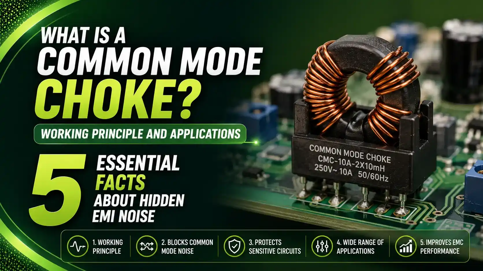
Noise, called common mode, flows the same direction on both wires at once, returning through ground instead of the paired conductor. A common mode choke tells these two apart, using nothing but geometry.
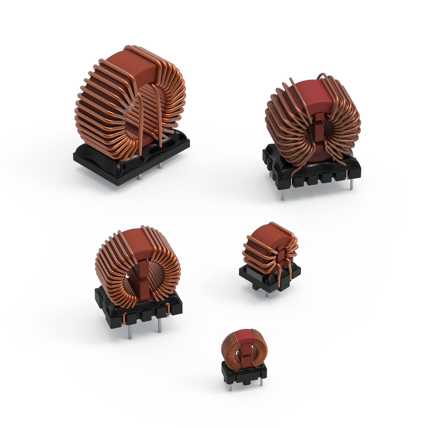
5 Essential Facts About How a Common Mode Choke Works
Understanding these five points covers nearly everything needed to specify and troubleshoot a common mode choke.
Two Windings, One Core, Opposing Direction
Both signal wires wind through the same core, but in a direction chosen so their intended fields oppose each other.
Differential Flux Cancels
Real signal current flows opposite directions on the two wires, so the magnetic fields it creates cancel out inside the core almost entirely.
Common Mode Flux Reinforces
Noise current flows the same direction on both wires, so its fields add together, creating strong impedance that blocks the noise.
Never Used Entirely Alone
Paired with Y capacitors to ground and often an X capacitor or differential choke, forming a complete EMI filter stage.
Has Real Saturation and Frequency Limits
Imperfect flux cancellation (leakage inductance) can saturate the core, and inter-winding capacitance rolls off performance at high frequency.
Differential Mode Signal vs Common Mode Noise
Telling these two apart is the entire reason this component exists.
Differential Mode (Wanted Signal)
Flows out on one wire, back on the other. Fields cancel in the choke core, so the signal passes through almost unaffected.
Common Mode (Unwanted Noise)
Flows the same direction on both wires, returning through ground. Fields reinforce in the choke core, creating strong blocking impedance.
A Complete EMI Filter, Not Just One Part
A common mode choke rarely works alone in a real design. It's one stage in a small filter network.
The choke raises common mode impedance, but that noise energy has to go somewhere. Without the Y capacitors giving it a controlled return path to ground, the choke alone is only half a filter.
Core Saturation: A Real Design Limit
Perfect flux cancellation is theoretical. Real windings have small imbalances, called leakage inductance, that matter at high current.
Result Bmax in Gauss, must stay below the core material's saturation flux density
Typical ferrite saturation limit: roughly 3000 to 4000 Gauss (300 to 400 mT)
Exceeding this limit collapses inductance and choke performance at that current
Common Mode Choke vs Differential Mode Choke vs Ferrite Bead
These three components look similar but solve different problems.
| Component | Windings | Blocks | Passes |
|---|---|---|---|
| Common Mode Choke | Two, opposing wind direction | Common mode noise | Differential signal, nearly unaffected |
| Differential Mode Choke | Single winding per line | Differential mode noise | Common mode current freely |
| Ferrite Bead | Single pass-through conductor | High frequency noise (broadband) | DC and low frequency signal |
Where Common Mode Chokes Are Used
Switching Power Supplies
AC input filtering ahead of the rectifier stage.
USB, HDMI, Ethernet
Protecting high speed differential data pairs from radiated noise.
Motor Drives and Inverters
Three-phase common mode chokes suppress VFD switching noise.
Medical Equipment
Meeting strict conducted emission limits near sensitive electronics.
Automotive Electronics
AEC-Q200 qualified chokes on CAN, LIN, and power lines.
Industrial Fieldbus Networks
10Base-T1L and similar industrial Ethernet noise suppression.
Do's and Don'ts of Common Mode Choke Selection
✓ Do
- Match the self resonant frequency to the dominant noise frequency
- Check both common mode and differential mode impedance specs
- Place the choke as close to the noise source or connector as possible
- Size current rating with margin, since DC bias reduces effective inductance
✗ Don't
- Rely on inductance alone specified at 1 kHz for high frequency filtering
- Assume a common mode choke alone solves differential mode noise too
- Ignore leakage inductance when checking for core saturation risk
- Skip verification with real impedance or insertion loss curves
Live Core Saturation Risk Calculator
Enter leakage inductance, current, turns, and core area to estimate peak flux density and saturation risk.
Why Insertion Loss Changes With Frequency
A common mode choke's effectiveness isn't flat across the spectrum. It follows a distinct curve shaped by two competing effects.
Below roughly 2 MHz, insertion loss tracks the choke's own impedance, which climbs steadily with frequency as expected from a simple inductor.
Above that point, inter-winding capacitance starts to dominate, and insertion loss begins rolling off. The frequency where insertion loss peaks is the self resonant frequency, and it should land close to the actual noise frequency being targeted.
Reference Materials on Common Mode Chokes
FAQs on Common Mode Chokes
External References
- Common-Mode Chokes: From Working Principles to Important Performance Parameters, All About Circuits
- A Guide to Understanding Common Mode Chokes, Coilcraft
- Common Mode Chokes Reduce Conducted Emissions, EMI Software
- Common Mode Chokes Tutorial, Würth Elektronik
- Line Filter Application Note, Würth Elektronik
What we learn today
- A common mode choke uses two windings on a shared core, wound so differential signal flux cancels while common mode noise flux reinforces.
- The result is near-zero impedance to the wanted signal and high impedance to noise flowing the same direction on both wires.
- Real chokes are rarely used alone, typically paired with Y capacitors that give blocked common mode noise a path to ground.
- Leakage inductance from imperfect winding coupling can saturate the core at high current, calculated using Bmax = 2piLI x 10^8 / (4.44NAe).
- Common mode chokes appear throughout switching power supplies, USB/HDMI/Ethernet lines, motor drives, and automotive electronics.