
An agitated vessel doesn't really have a level. It has a churning, foaming, sloping mess that a transmitter has to somehow interpret as one.
Most bad level readings in reactors trace back to one of a handful of fixable decisions, not a faulty instrument.
Level measurement in agitated vessels comes down to picking a technology that tolerates turbulence and foam, then mounting and configuring it so a churning surface still reads as one stable number.
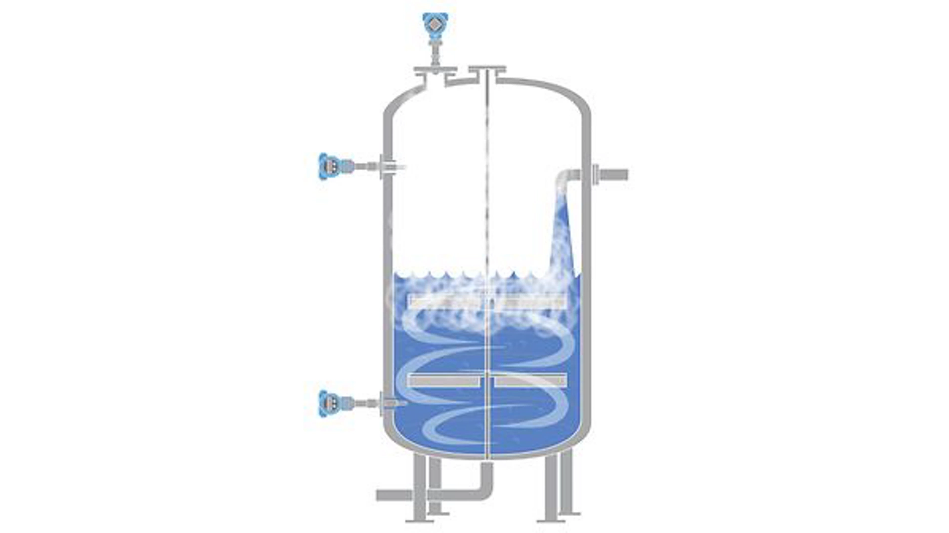
Mixing creates exactly the conditions most level technologies were never designed for. The surface moves, air gets folded in, and a vortex can pull liquid toward the walls.
This builds directly on the radar false echo handling and damping response time topics already covered on this site, since agitated vessels push both problems to their limit at once.
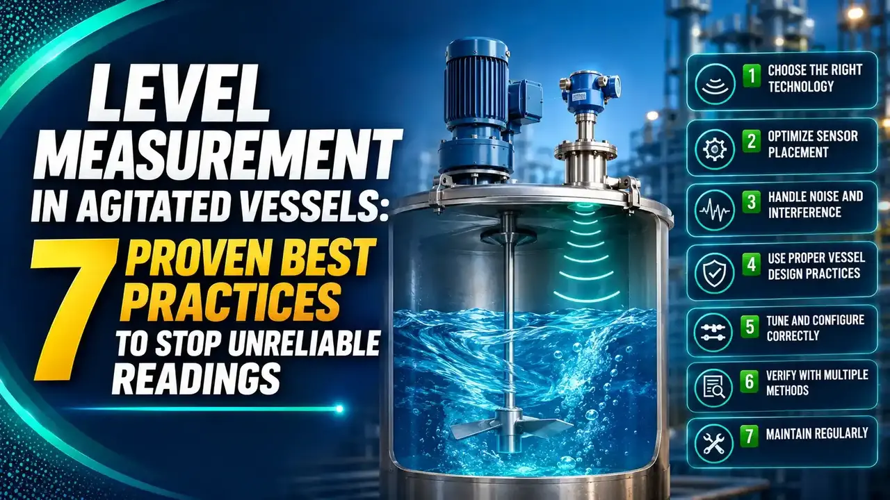
7 Best Practices for Level Measurement in Agitated Vessels
These seven decisions account for most of the difference between a stable loop and a constant maintenance headache.
Pick a Technology That Tolerates Turbulence
Guided wave radar and FMCW non-contact radar handle agitation far better than ultrasonic or basic capacitance.
Mount Away From the Agitator's Sweep
Never mount directly above a shaft or blade path. Offset the nozzle and keep clearance from the tank wall.
Add a Stilling Well or Bypass Chamber When Needed
A calm measurement column removes turbulence and foam from the equation entirely for most technologies.
Run False Echo Mapping After Installation
Agitator blades and baffles need to be learned and suppressed as part of commissioning, not left to chance.
Tune Damping to the Actual Agitation Cycle
Enough filtering to smooth turbulence noise, not so much that real level changes get masked.
Account for Foam Signal Loss
A foam layer as thin as 50mm can scatter a large fraction of a radar signal's return energy.
Accept That a Vortex Has No True Level
Some agitated conditions genuinely have no single correct level value, only a best estimate.
Stilling Well vs Bypass Chamber
Both calm a turbulent surface, but they attach to the vessel completely differently.
Stilling Well
An internal pipe mounted inside the vessel itself, with holes near the bottom letting liquid reach the same level without surface chaos.
Bypass Chamber
An external side-mounted pipe connected via top and bottom process taps, acting as a communicating vessel outside the tank.
Why Agitation Breaks Level Measurement
Three distinct physical effects stack on top of each other in a mixed vessel, and each one attacks a different part of the measurement.
A stilling well solves turbulence and foam cleanly. It does not solve a vortex. If a strong enough swirl moves liquid across the bottom of the well itself, the well can start behaving like a pitot tube, reading artificially high.
Level Technology vs Agitation Tolerance
Not every technology degrades the same way under mixing.
| Technology | Agitation Tolerance | Key Limitation |
|---|---|---|
| Guided Wave Radar (GWR) | Very good | Coating can mask the probe's reflection over time |
| FMCW Non-Contact Radar | Good to very good | Needs stilling well for low dielectric, heavy foam service |
| Differential Pressure (DP) | Moderate | Density changes from mixing directly bias the reading |
| Capacitance | Moderate | Entrained air/bubbles change the effective dielectric |
| Ultrasonic | Poor to moderate | Foam and blade reflections both degrade the echo badly |
| Nucleonic (Radiometric) | Excellent | No physical contact at all, but higher cost and regulatory burden |
Where Agitated Vessel Best Practices Apply
Chemical Reactors
Batch reactors with top-entry agitators and heating coils.
Blending Tanks
Paint, adhesive, and specialty chemical blending vessels.
Bioreactors
Stirred tank bioreactors with impeller-driven mixing.
Wastewater Aeration
Heavily aerated basins with constant surface disturbance.
Food and Beverage Mixing
Hygienic mixing vessels needing foam-tolerant measurement.
Crude and Fuel Blending
Low dielectric hydrocarbon blending with agitation.
Mounting Behind a Baffle: An Overlooked Option
Stilling wells aren't the only mechanical answer. In some reactors, positioning the sensor behind an existing internal baffle works just as well.
A baffle plate breaks up the swirling flow pattern the agitator creates, giving a calmer local zone without adding new hardware to the vessel.
This only works if a baffle already exists in a useful position, or if one can be added during a turnaround, so it's more of an opportunistic fix than a universal solution.
Do's and Don'ts for Agitated Vessel Level Measurement
✓ Do
- Position the antenna or probe offset from the agitator's sweep path
- Use a stilling well or bypass chamber for heavy foam or turbulence
- Re-run false echo mapping after any change to internal fittings
- Ask whether the application needs true level or just inventory trend
✗ Don't
- Mount directly above the agitator shaft or blade sweep
- Assume a stilling well fixes a strong vortex on its own
- Apply heavy damping as a first fix without checking mounting position
- Use basic ultrasonic in a vessel with persistent foam or heavy agitation
Live Stilling Well Sizing Helper
Enter the antenna or probe diameter to get a recommended stilling well inside diameter and clearance.
Reference Materials on Agitated Vessel Level Measurement
FAQs on Level Measurement in Agitated Vessels
External References
- Stilling Wells for Radar Level Measurement, Sizing and Install Guide
- Level Measurement on Vortices, APG Sensors
- Why Engineers Choose Radar Level Measurement for Bypass Installations, SenTec
- Guidelines for Installing Guided Wave Radar in Chambers, Emerson
- Guidelines for Using Radar in Stilling Wells, Emerson
What we learn today
- Level measurement in agitated vessels fails mainly from technology choice, mounting position, or missing mechanical calming, not from a faulty instrument.
- Guided wave radar and FMCW non-contact radar tolerate agitation far better than ultrasonic or basic capacitance technology.
- Stilling wells (internal) and bypass chambers (external) both calm turbulence and foam, but they solve the problem differently.
- A 50mm foam layer can scatter roughly 30 dB of radar signal, and a mixer-driven surface can move 100mm/s or faster.
- A strong vortex has no single true level, and even a stilling well can behave like a pitot tube if the swirl reaches its bottom openings.