
Damping doesn't hold a reading steady for a few seconds and then jump. It's a mathematical filter, and it never stops working.
Set it wrong and the transmitter starts quietly lying to the control system about how fast the process is actually moving.
Pressure transmitter damping and response time describe how quickly a transmitter's output catches up to a real change in process pressure, using an adjustable first-order filter.
Damping exists to solve one problem: real pressure signals are noisy. Turbulence, pump pulsation, and valve chatter all show up as jitter on the output.
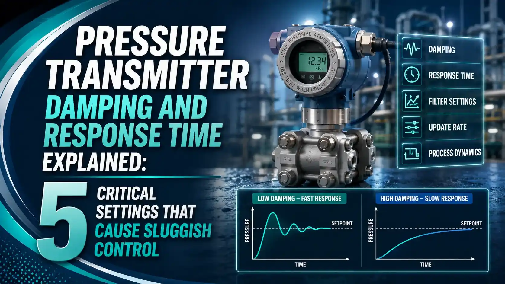
Damping smooths that jitter out. The tradeoff is speed, since the same filter that removes noise also slows down the transmitter's response to a genuine, fast pressure change.
The 5 Damping Time Constant Milestones
A transmitter's damped output follows the exact same exponential curve as an RC time constant circuit, reaching fixed percentages at each multiple of the damping time.
63.2% Complete
At one damping time constant, the output has closed 63.2% of the gap to the true value.
86.5% Complete
Progress slows as the reading approaches the actual process value.
95.0% Complete
Often close enough for rough operator trend reading.
98.2% Complete
The remaining gap is small for most control purposes.
99.3% Complete
The standard engineering rule of thumb for "settled" response.
Damping vs Dead Time (Mechanical Response Time)
Total response time is made of two completely different delays, and only one of them is adjustable.
Dead Time (MRT)
The physical time for pressure to travel from the process diaphragm to the sensing element. Fixed by hardware design, typically 90 to 150 ms.
Damping (Software Filter)
A deliberate first-order filter applied after the measurement, adjustable from 0 up to 100 seconds depending on the transmitter model.
How Total Response Time Is Built
What a control system actually experiences is the sum of both delays, not just the damping setting alone.
A 5 second damping setting doesn't mean the display freezes for 5 seconds. The output starts moving immediately and needs roughly 25 seconds, 5 times the damping constant, to settle within 1% of the true value.
Damping Formula and Worked Example
The math behind damping is the same first-order exponential used in any RC filter.
Pin = size of the step change in process pressure
τ = damping time constant (seconds)
Example: Step change of 20 psi, damping τ = 5 seconds, t = 5 seconds
Pout = 20 x (1 - e^(-5/5)) = 20 x (1 - 0.368) = 12.6 psi
At t = 25 seconds (5τ), output reaches about 19.86 psi (99.3%)
Typical Damping Settings by Application
Damping should be scaled to the process, not left at a factory default.
| Application | Typical Time Constant | Reasoning |
|---|---|---|
| Fast flow control loops | 0.1 to 0.5 seconds | Fast process dynamics need minimal added lag |
| General pressure monitoring | 1 to 3 seconds | Balances noise rejection with responsiveness |
| Level measurement (large vessels) | 2 to 10 seconds | Slow process tolerates more smoothing |
| Safety instrumented function (SIF) sensors | Minimal, per SRS requirement | Fast, verified response time is often safety critical |
A common rule of thumb sets damping at roughly 10 to 25 percent of the process time constant for control loop applications.
Where Damping Settings Matter Most
Flow Control Loops
Excess damping causes cycling when paired with aggressive PID tuning.
Level Loops
Slow processes tolerate heavier damping without hurting control quality.
Safety Instrumented Functions
Total response time must meet the safety requirements specification exactly.
Compressor Surge Protection
Fast surge events demand minimal damping and fast update rates.
Custody Transfer
Damping settings must match the accuracy requirements of billing contracts.
Noisy Pump Discharge
Turbulent, pulsating pressure signals benefit from moderate damping.
Damping vs Update Rate: Two Independent Settings
Engineers often confuse how often a value refreshes with how heavily that value is filtered. They aren't the same thing.
A transmitter can internally sample and calculate a new reading every 100 to 500 milliseconds. That's the update rate, and it's usually fixed by the device's internal architecture.
Damping operates on top of that update rate, smoothing the sequence of raw readings into the gradual exponential curve seen on the output. A fast update rate with heavy damping still produces a slow-looking response.
Do's and Don'ts of Setting Transmitter Damping
✓ Do
- Scale damping to the actual process time constant, not a factory default
- Verify total response time against SIF requirements when safety critical
- Check the analog output directly with a calibrator if display updates look odd
- Reduce damping first when a control loop shows sluggish, lagging response
✗ Don't
- Assume heavy damping is always "safer" for stability
- Confuse display update rate with the underlying damping time constant
- Apply the same damping value to every transmitter regardless of service
- Forget that aggressive PID tuning can fight excessive damping and cause overshoot
Live Damping Response Calculator
Enter the step change size, damping time constant, and elapsed time to see how much of the change the transmitter has actually reported.
Reference Materials on Damping and Response Time
FAQs on Pressure Transmitter Damping and Response Time
External References
- Transmitter Damping Adjustments, Control.com Textbook
- Process Variable Damping of Transmitter, Inst Tools
- What Is the Best Transmitter Damping or Signal Filter Setting?, Control Global
- Pressure Transmitter Response Time, FGP-140, Yokogawa
- Rosemount 3051 Pressure Transmitter Manual, Emerson
What we learn today
- Pressure transmitter damping and response time both hinge on the same first-order filter formula used in RC electrical circuits.
- Damping reaches 63.2%, 86.5%, 95.0%, 98.2%, and 99.3% of a step change at 1 through 5 damping time constants.
- Total response time combines a fixed mechanical dead time with the adjustable damping filter, and only damping can be changed in the field.
- Damping should be scaled to the process, roughly 10 to 25 percent of the process time constant, not left at a factory default.
- Excessive damping can destabilize an aggressively tuned control loop by making a fast process look artificially slow.