
An orifice plate paired with a differential pressure transmitter is the most common flow measurement setup in oil and gas plants, thanks to its low cost and simple installation. But that simplicity comes with a real limitation: rangeability.
The orifice only allows about 3:1 rangeability to maintain accuracy, meaning a meter sized for 10 MMscfd maximum flow can only reliably measure down to around 3.3 MMscfd.
This limitation is not a flaw in the equipment, it is a direct mathematical consequence of the square root relationship between flow and pressure drop, the same relationship behind pressure transmitter based DP flow measurement generally.
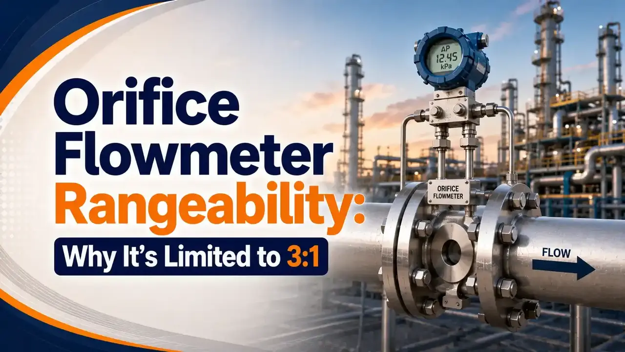
This guide covers the orifice flow equation, why sensitivity degrades sharply at low flow, a full worked example showing the effect in real numbers, and how some installations extend rangeability well beyond the traditional 3:1 limit.
What Is Flowmeter Rangeability?
Rangeability, or turndown ratio, describes the ratio between a meter's maximum reliable flow reading and its minimum reliable flow reading, a concept that also shapes the straight pipe run and installation guidance in our broader look at flow meter reading stability. An orifice flowmeter, combined with a DP transmitter, typically allows only 3:1 rangeability while maintaining accuracy.
This means that if a meter is sized for a maximum flow of 10 MMscfd, the minimum flow it can reliably measure is only about 3.3 MMscfd, roughly one third of its maximum span. Below that point, accuracy degrades faster than most applications can tolerate.
The Orifice Flow Equation
According to the Bernoulli principle, the relationship between flow and the pressure drop across an orifice is expressed by the following formula.
- Q is the volumetric flow rate
- Cf is a discharge constant specific to the orifice geometry
- Ao is the cross sectional orifice area
- dP is the measured pressure drop
- ρ is the fluid density
Flow value is obtained by measuring pressure drop, and the relationship between the two is a square root, not a straight line. This single mathematical fact is the entire reason rangeability is limited.
.svg)
Why Sensitivity Degrades at Low Flow
Consider an orifice intended for flow measurement of 0 to 10 MMscfd, represented by a 0 to 100 inH2O pressure drop range. At maximum flow, a 1% change in flow, from 10 MMscfd down to 9.9 MMscfd, is represented by roughly a 2% change in DP, from 100 inH2O down to about 98.01 inH2O.
Because of the square root relationship, that same 1% flow change represents a much larger swing in DP as flow rate drops. The lower the flow being measured, the more sensitivity suffers, exactly why the measurement resolution of the transmitter itself becomes the limiting factor at low flow.
| Flow (% of Max) | DP (% of Full Scale) | DP Change for 1% Flow Change |
|---|---|---|
| 100% | 100% | ~2.0% of DP span |
| 75% | 56.3% | ~2.7% of DP span |
| 50% | 25% | ~4.0% of DP span |
| 33% (3:1 turndown limit) | ~11% | ~6.1% of DP span |
| 25% | 6.25% | ~8.0% of DP span |
| 10% | 1% | ~20% of DP span |
At 10% of maximum flow, a tiny 1% flow change demands the transmitter resolve a DP change five to ten times larger, proportionally, than it would at full flow. That is the real reason orifice meters run out of usable accuracy so quickly below about a third of their span.
🧮 Interactive Orifice DP vs Flow Calculator
Enter your maximum flow and maximum DP, then a flow percentage, to see the corresponding DP and the sensitivity at that point.
Watch: DP Transmitter Square Root Calculation Examples
This video walks through maximum flow and DP calculation examples for a differential pressure transmitter, directly building on the relationship covered above.
Video: "Differential Pressure Transmitter Square Root Calculation Examples", via YouTube.
Extending Rangeability Beyond 3:1
The traditional 3:1 limit is not an absolute ceiling. Using a multivariable transmitter, which compensates for pressure and temperature effects directly at the transmitter rather than relying on fixed assumptions, similar in spirit to the compensation approach in RTD temperature measurement, rangeability can be extended to around 10:1 in practice.
Changing the transmitter to a higher accuracy or higher resolution model, or resizing the orifice plate itself for the actual expected flow range, are two other practical ways engineers commonly stretch rangeability well past the basic 3:1 rule, similar in principle to how Coriolis flow meters maintain far higher turndown ratios through a fundamentally different measurement principle.
FAQs on Orifice Flowmeter Rangeability
You May Also Like
Coriolis Flow Meter Uncertainty and Inaccuracy: How to Calculate It
When an application genuinely needs better rangeability than an orifice plate can offer, Coriolis meters are a common next step. This guide covers how to calculate their real measurement uncertainty using vendor specifications and a live calculator.
Read Full Article →External References
- Orifice Plate, Wikipedia
- Bernoulli's Principle, Wikipedia
- ISO 5167, Measurement of Fluid Flow by Means of Pressure Differential Devices
What we learn today
- Orifice flowmeter rangeability is traditionally limited to about 3:1 to maintain accuracy, a direct consequence of the square root relationship between flow and pressure drop.
- The orifice flow equation, Q = Cf × Ao × √(dP/ρ), is derived directly from the Bernoulli principle.
- A 1% flow change near maximum flow produces roughly a 2% DP change, and that ratio grows sharply worse as flow rate drops.
- Below about a third of maximum flow, transmitter resolution becomes the limiting factor on measurement accuracy.
- Multivariable transmitters and careful orifice sizing can extend practical rangeability well beyond the traditional 3:1 limit, up to around 10:1.