
Every transistor oscillator does the same basic job, turning DC into a continuous, undamped AC waveform, but the six main types get there through completely different tank and feedback arrangements, and mixing them up costs real design time.
Types of transistor oscillators fall into three families: LC oscillators for high frequencies, RC oscillators for low frequencies, and crystal or negative resistance oscillators for fixed or very high frequency needs.
A transistor oscillator generates continuous, undamped oscillations at a chosen frequency once a tank circuit and a feedback network are correctly connected to it. Every type does this same basic job under a different name, Hartley, Colpitts, Wien bridge, phase shift, crystal, negative resistance, but they differ sharply in how they replace the energy the tank circuit constantly loses, and in the frequency range each one actually covers well.
The full sinusoidal frequency spectrum engineers need to cover runs from under 1 Hz to many GHz, and no single oscillator design handles that entire range well. That's exactly why six distinct active and passive component arrangements exist side by side, each one advantageous over a different slice of the spectrum.
How a Transistor Sustains Continuous Oscillation
Every type of transistor oscillator relies on the same underlying mechanism to keep oscillating instead of dying out.
Tank Circuit Rings
An LC or RC network briefly oscillates on its own, but resistive losses would normally damp it out.
Feedback Samples Output
A portion of the output signal is tapped and routed back to the transistor's input.
Transistor Amplifies in Phase
The active device restores the energy lost to resistance, with the feedback arriving in phase.
Oscillation Sustains
Once loop gain equals 1 and phase shift totals 360 degrees, the output becomes a stable, continuous waveform.
The Barkhausen Criterion for Transistor Oscillators
Every one of these types of transistor oscillators must satisfy the same two mathematical conditions before sustained oscillation is even possible.
The 4 Families of Types of Transistor Oscillators
Every named oscillator circuit belongs to one of four broad families, grouped by how the tank circuit is built.
LC Oscillators
Use an inductor and capacitor tank circuit. Hartley and Colpitts are the two most widely used designs, covering roughly 10 kHz to 100 MHz.
RC Oscillators
Use resistor-capacitor networks instead of bulky low-frequency inductors, covering roughly 1 Hz to 10 MHz.
Crystal Oscillators
Use a quartz crystal's mechanical resonance instead of an LC or RC network, locking to one exceptionally stable, fixed frequency.
Negative Resistance Oscillators
Use a device that presents negative resistance across part of its characteristic curve to directly cancel tank circuit losses at very high frequencies.
Hartley Oscillator: Tapped Inductor Feedback
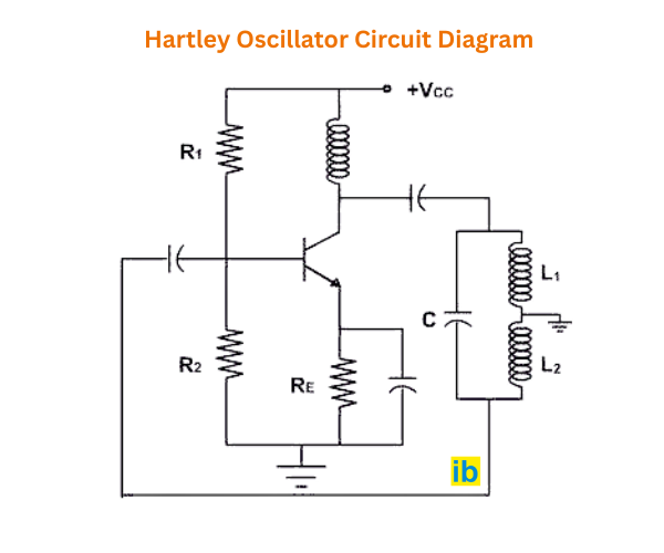
The Hartley oscillator, first built by Ralph Hartley in 1915, splits the tank circuit's inductance into two coils, L1 and L2, connected in series with a single tuning capacitor across the pair. The feedback signal is tapped from the junction between the two coils and fed back in phase to the transistor's input.
Colpitts Oscillator: Tapped Capacitor Feedback
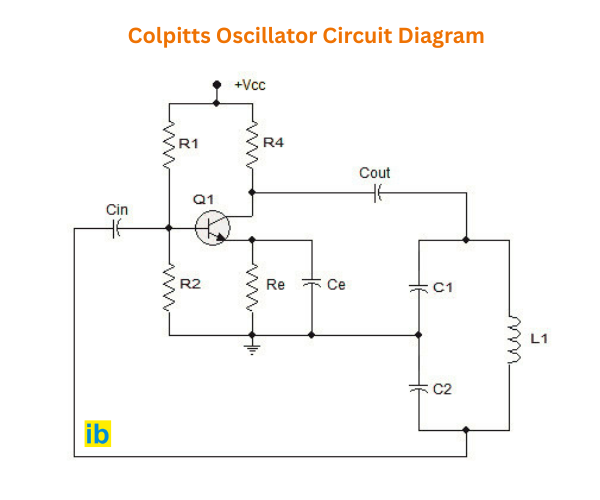
The Colpitts oscillator, invented by Edwin Colpitts in 1918, is the electrical dual of the Hartley design. Instead of splitting the inductor, it splits the capacitance into two series capacitors, C1 and C2, across a single inductor, and taps feedback from their junction.
LC Oscillator Frequency Formula and Worked Example
Both Hartley and Colpitts oscillators share the same underlying resonance formula, just with a different equivalent inductance or capacitance plugged in depending on which element got split.
Wien Bridge and Phase Shift: The Two RC Oscillators
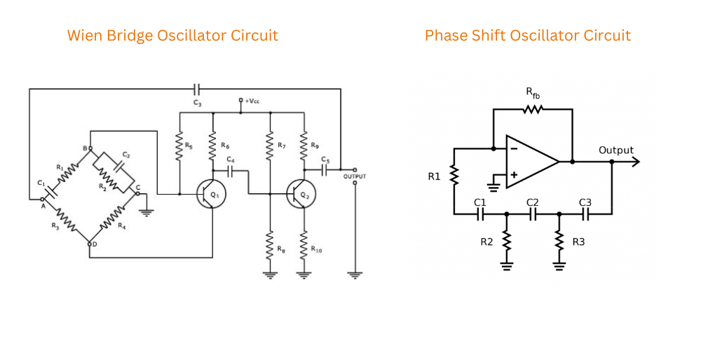
Below about 1 MHz, the inductors an LC tank would need become too bulky and heavy to be practical, so RC networks take over instead. The Wien bridge oscillator uses a lead-lag RC network in the feedback path and needs a gain of at least 3 to sustain oscillation. The phase shift oscillator instead cascades three RC sections, each contributing 60 degrees of phase shift, to reach the full 180 degrees needed alongside an inverting amplifier stage.
Crystal and Negative Resistance Oscillators
A crystal oscillator replaces the LC or RC tank entirely with a quartz crystal, which mechanically resonates at one extremely stable frequency set by how the crystal is physically cut. The crystal behaves electrically like an extremely high-Q LC circuit, but one built from a slice of quartz rather than discrete components, so its resonant frequency barely drifts with temperature, supply voltage, or component aging.
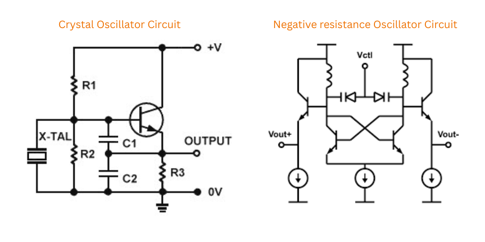
This is why crystal oscillators anchor clock circuits and radio references where drift simply isn't acceptable. A microcontroller's system clock, a radio receiver's local oscillator reference, and a wristwatch timebase all lean on this same fixed-frequency stability rather than any tunability, since none of those applications ever needs to sweep across a frequency range.
Negative resistance oscillators work differently again. Certain devices, tunnel diodes among them, present a negative resistance region on their current-voltage curve, meaning current actually decreases as voltage increases across part of that curve. Connected across an LC tank, that negative resistance directly cancels the tank's normal resistive losses, letting oscillation sustain itself well above 100 MHz where ordinary transistor current gain starts running out and conventional feedback oscillators become difficult to build reliably.
Types of Transistor Oscillators Compared by Frequency Range
Seeing all six types of transistor oscillators side by side makes it obvious why each one exists in the first place.
| Oscillator Type | Tank Circuit | Approximate Frequency Range | Frequency Stability |
|---|---|---|---|
| Wien Bridge Oscillator | RC lead-lag network | 1 Hz to 1 MHz | Good, needs gain-stabilizing feedback |
| Phase Shift Oscillator | Three-stage RC network | 1 Hz to 10 MHz | Moderate |
| Hartley Oscillator | Tapped inductor, single capacitor | 10 kHz to 100 MHz | Good |
| Colpitts Oscillator | Single inductor, tapped capacitor | 10 kHz to 100 MHz | Very good |
| Negative Resistance Oscillator | LC tank with negative resistance device | Above 100 MHz | Moderate to good |
| Crystal Oscillator | Quartz crystal resonator | Fixed frequency | Excellent |
Choosing Between LC and RC Oscillator Types
✓ LC Oscillators Work Well When
- The target frequency sits above roughly 10 kHz
- Board space allows for a small tuning inductor
- Very good frequency stability is needed, favoring Colpitts
- The application is RF: radio, wireless links, local oscillators
✗ RC Oscillators Are the Better Fit When
- The target frequency is below roughly 1 MHz
- A bulky, heavy inductor isn't practical for the design
- A pure, low-distortion sine wave is the priority, favoring Wien bridge
- The application is audio, instrumentation, or signal generation
Live LC Oscillator Frequency Calculator
Enter the tank inductance and equivalent capacitance for a Hartley or Colpitts oscillator to calculate its resonant frequency using the standard tank circuit formula.
Reference Materials on Transistor Oscillators
FAQs on Types of Transistor Oscillators
External References
- Hartley Oscillator and Hartley Oscillator Theory, Electronics Tutorials
- Colpitts Oscillator Tutorial and Design, Electronics Tutorials
- Colpitts Oscillator, HandWiki
- Oscillators, Unit 11 Course Notes, IGNOU
- Phase Shift, Wien Bridge, Hartley and Colpitts Oscillators, Lecture Notes
What we learn today
- All types of transistor oscillators do the same job, converting DC into continuous undamped AC, but differ in tank circuit design and usable frequency range.
- Hartley taps feedback from a split inductor, Colpitts from a split capacitor pair, and both share the same LC resonance formula.
- Wien bridge and phase shift are the two common RC oscillators, taking over below roughly 1 MHz where inductors become impractical.
- Every oscillator, regardless of type, must satisfy the Barkhausen criterion: loop gain of 1 and total phase shift of 360 degrees.
- Crystal oscillators trade tunability for exceptional frequency stability, while negative resistance oscillators extend operation above 100 MHz.