
An encoder compresses many input lines into a compact binary code. A decoder does the exact opposite. Here is exactly how encoder vs decoder circuits differ, with real IC datasheets and a live simulator you can click through.
What Are Encoders and Decoders?
An encoder and a decoder are mirror images of each other. One compresses many input lines down to a compact code, the other expands a compact code back out to many output lines.
Both are combinational circuits, meaning their output depends only on the current input, with no memory involved. That puts them in a different family from the flip-flop types we covered previously, which do store state.
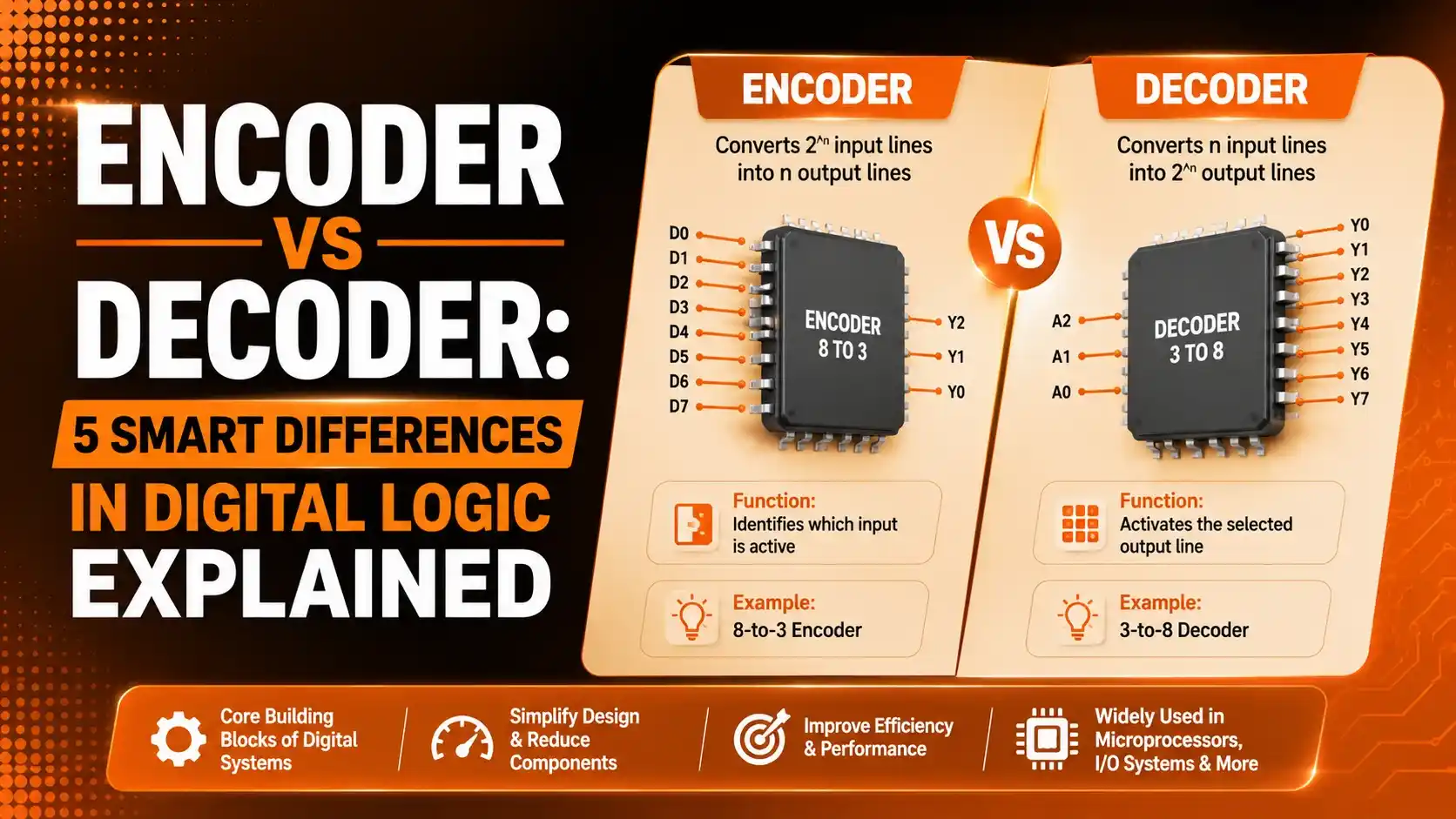
An encoder takes 2^n input lines and produces an n-bit binary code representing which line is active. A decoder does the reverse, taking an n-bit code and activating exactly one of 2^n output lines. You already saw a related idea in PLC shift registers, where a bit pattern tracks position along a physical line, similar in spirit to how a decoder tracks which single output should activate.
This guide covers encoder vs decoder circuits in full, with real datasheet examples, a worked binary example, and a simulator where you can click inputs and watch the output respond live.
Both circuit families sit at the foundation of nearly every digital system you interact with daily. Every time a computer reads one of hundreds of possible keys, or selects one specific memory location out of millions, an encoder or decoder is quietly doing the work behind the scenes.

How Encoders and Decoders Process Binary Information
Both circuit types follow the same underlying logic, just running in opposite directions.
Input Lines Are Driven
An encoder receives one active line among many. A decoder receives a fixed-width binary code instead.
OR Gates Combine or Select
Internal OR gate logic either combines active lines into a code, or selects a single line from a code.
Output Reflects the Result
The encoder outputs a compact n-bit code. The decoder outputs a single active line among 2^n.
Circuit Reacts Instantly
As a combinational circuit, there is no clock involved, the output updates the moment inputs change.
Encoder vs Decoder: Core Definitions
Before comparing the details, it helps to see each definition side by side.
Encoder
Takes 2^n input lines, of which typically only one is active, and produces an n-bit binary code identifying which input was active.
Best for: compressing many signal lines into a compact code.
Decoder
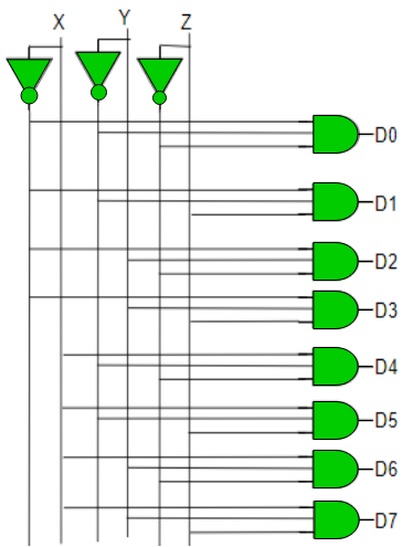
Takes an n-bit binary code and activates exactly one of 2^n output lines, leaving all others inactive.
Best for: selecting or activating one specific device from many.
What is happening: The encoder and decoder are functional opposites built from the same basic OR gate logic, just wired in reverse directions relative to each other.
A real example: A computer keyboard uses an encoder to compress 100-plus individual key switches down into a compact scan code. A memory system uses a decoder to expand a compact address code back out to select one specific memory chip.
Why it works: Since 2^n grows so much faster than n, this pair of circuits lets a small number of wires represent and control a very large number of physical lines.
Encoder vs Decoder: The Binary Math
The relationship between input and output line counts follows one simple rule in both directions.
Encoder: 2^n input lines → n output lines
Decoder: n input lines → 2^n output lines
Worked example: n = 3
Encoder: 2^3 = 8 inputs, 3 outputs
Decoder: 3 inputs, 2^3 = 8 outputs
That single relationship is why an 8-to-3 encoder and a 3-to-8 decoder are natural partners, real ICs like the 74148 and 74138 are frequently used right next to each other in the same design.
5 Smart Differences Between Encoder and Decoder
These five distinctions come up constantly in coursework and real digital design work, and they are the core of every encoder vs decoder comparison.
Direction of Data Flow
An encoder narrows many lines down to a few. A decoder widens a few lines back out to many. They are functional opposites of each other.
Active Input Assumption
A basic encoder assumes only one input line is active at a time, and gives an undefined result otherwise. A decoder has no such assumption, since its input is already a clean binary code.
Priority Handling
Priority encoders exist specifically to resolve the case where multiple inputs go active together. Standard decoders never face this problem, since their binary input is unambiguous by definition.
Enable and Strobe Inputs
Decoders commonly include one or more enable or strobe inputs, useful for chip-select style operation. Basic encoders typically do not include this feature.
Real-World Role
Encoders compress and detect, identifying which of many lines is active. Decoders select and activate, choosing exactly one output from a compact code.
Notice that all five differences trace back to the same root cause: an encoder's job is to reduce ambiguity down to a single answer, while a decoder's job is to expand a single answer back out into a physical selection. Once that root idea clicks, every other distinction between encoder vs decoder circuits follows naturally.
Real Encoder and Decoder ICs
Seeing real part numbers makes the encoder vs decoder distinction concrete. Click each tab to compare.
The 74148 is an 8-line to 3-line priority encoder. If two or more of its eight inputs go active together, the highest-numbered input wins, and cascading pins allow multiple 74148 chips to be chained for wider encoding.
The 74138 is a 3-line to 8-line decoder, commonly used for memory chip select logic. It includes three enable inputs, two active low and one active high, which reduce the external gates needed when expanding a system.
The 74147 encodes nine data lines directly to 4-bit BCD output, aimed squarely at decimal keypad and numeric entry applications rather than pure binary encoding.
The CD4028 is a BCD-to-decimal decoder, converting a 4-bit BCD input into one of ten active output lines, widely used for driving numeric indicator lamps and simple display selection circuits.
Encoder vs Decoder Comparison Table
| Feature | Encoder | Decoder |
|---|---|---|
| Input Count | 2^n lines | n lines |
| Output Count | n lines | 2^n lines |
| Priority Logic Needed | Yes, for multiple active inputs | No |
| Common Enable Input | Rare | Common |
| Example IC | 74148, 74147 | 74138, CD4028 |
Applications of Encoders and Decoders
These six applications show up constantly in real digital systems, from the keyboard you are typing on to the memory chips inside it.
Keyboard Encoding
An encoder compresses dozens of key switches into a compact scan code.
Priority Interrupt Controllers
A priority encoder identifies the highest-priority pending interrupt line.
Memory Address Decoding
A decoder selects exactly one memory chip from a binary address code.
Seven-Segment Display Drivers
A BCD decoder converts a 4-bit digit code into the correct segment pattern.
Data Compression
Encoders reduce the number of physical lines needed to represent many states.
Communication Systems
Decoders interpret received binary codes back into their original meaning.
Advantages and Limitations of Encoder vs Decoder Circuits
Why This Pair Works So Well Together
Limitations to Keep in Mind
Try It: Encoder and Decoder Simulator
Switch between encoder and decoder mode, click an input, and watch the output respond according to real digital logic.
Download Encoder and Decoder References
These two official datasheets cover the real ICs referenced throughout this guide.
SNx4HC148 8-Line to 3-Line Priority Encoders
Official Texas Instruments datasheet covering the 74148 priority encoder
SNx4HC138 3-Line to 8-Line Decoders/Demultiplexers
Official Texas Instruments datasheet covering the 74138 decoder
Watch: Introduction to Encoders and Decoders
This video from Neso Academy covers encoder and decoder fundamentals with clear worked examples.
FAQs on Encoder vs Decoder
External References
- Texas Instruments, SNx4HC148 8-Line to 3-Line Priority Encoders Datasheet
- Texas Instruments, SNx4HC138 3-Line to 8-Line Decoders/Demultiplexers Datasheet
- GeeksforGeeks, Encoders and Decoders in Digital Logic
- YouTube, Neso Academy, Introduction to Encoders and Decoders
What we learn today
- Encoder vs decoder comes down to direction: an encoder compresses 2^n inputs into an n-bit code, a decoder expands an n-bit code back into 2^n outputs.
- Priority encoders resolve the case where multiple inputs go active at once, a problem decoders never face.
- Real ICs like the 74148 encoder and 74138 decoder are natural partners, often used side by side.
- Enable inputs are common on decoders, letting several chips share address lines in larger systems.
- Both circuits are purely combinational, with no clock or memory involved, unlike flip-flops.