
The SCR is only one member of a much larger family. Here is exactly how thyristors and triacs differ, why a triac can switch AC in both directions, and how a light dimmer actually chops the mains waveform, with a real firing-angle simulator you can try.
What Is a Thyristor?
Thyristor is not the name of one device. It is the family name for an entire group of four-layer semiconductor switches, and the SCR is just the most famous member of that family.
Our earlier guide on silicon controlled rectifiers covers the SCR itself in detail, the classic unidirectional thyristor used to convert AC into controlled DC. This guide goes beyond that single device, into the TRIAC, the DIAC, and the broader thyristor family they all belong to.
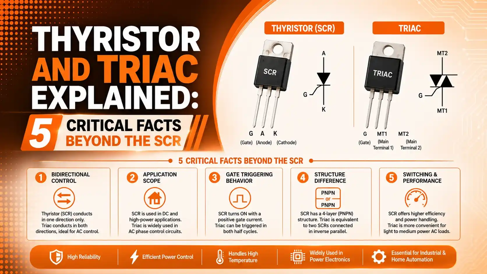
What unites every member of this family is a four-layer PNPN structure and a shared behavior: once triggered into conduction, the device latches on and stays on by itself, needing no further gate signal until the main current drops to nearly zero.
The Thyristor Family Tree
Beyond the SCR, thyristors and triacs branch into several genuinely different devices, each solving a slightly different power control problem.
SCR
Unidirectional, 3 terminals
TRIAC
Bidirectional, 3 terminals
DIAC
Bidirectional, 2 terminals, no gate
GTO
Unidirectional, gate turn-off
5 Facts About Thyristors and Triacs
These five facts about thyristors and triacs explain almost every practical question that comes up once you move past the basic SCR into the wider family.
Thyristor Is a Family Name, Not One Device
SCR, TRIAC, DIAC, GTO, and several less common variants all share the same four-layer PNPN structure. The SCR is simply the most widely used member, not a synonym for the whole family.
SCR Is Unidirectional, TRIAC Is Bidirectional
An SCR only conducts current from anode to cathode, in one direction. A TRIAC behaves like two SCRs wired in reverse-parallel, letting it conduct current in both directions of an AC waveform.
Once Triggered, the Gate Loses Control
A brief gate pulse is all it takes to turn the device on. After that, the gate has no further influence, the device stays latched on until the main current falls below its holding current value.
TRIACs Usually Need a DIAC to Fire Symmetrically
Without help, a TRIAC's gate can be more sensitive in one direction than the other. Pairing it with a DIAC gives a consistent, symmetrical breakover voltage for reliable firing in both half-cycles.
Real Circuits Need Snubber Protection
A sudden voltage transient, not just the gate, can also trigger these devices unintentionally. A resistor-capacitor snubber network across the main terminals limits that risk in real installations.
Quadrant Operation: Where Each Device Can Conduct
Engineers describe thyristor and triac triggering using four quadrants, based on the polarity of the main voltage and the gate signal at the moment of firing.
Quadrant I
MT2 positive, gate positive. Most sensitive triggering region for a TRIAC.
Quadrant II
MT2 positive, gate negative. Usable, slightly less sensitive.
Quadrant IV
MT2 negative, gate positive. Least sensitive, often avoided by designers.
Quadrant III
MT2 negative, gate negative. Second most reliable triggering region.
Latching Behavior: Why the Gate Loses Control
This is the single most misunderstood property of the whole thyristor family. Once triggered, nothing the gate does matters until the current itself falls away.
Off State
No gate signal, device blocks voltage
Gate Pulse
Brief trigger current applied
Latched On
Device conducts, gate now has no effect
Natural Turn-Off
Current drops below holding current, device turns off
What is happening: The gate signal only needs to exist long enough to start conduction. Removing it immediately afterward changes nothing, since the device's own internal feedback keeps it latched.
A real example: In an AC circuit, this latching is actually convenient. The device naturally turns off every time the AC waveform crosses zero, since the main current briefly drops below the holding current at that instant, ready to be re-triggered on the next half-cycle.
Why it works: Because turn-off happens automatically at each zero crossing in AC applications, engineers only need to worry about precisely timing when to turn the device on, not how to turn it off, which is exactly the basis of phase-angle dimming.
Firing Angle and Phase Control
Delaying the gate pulse relative to the start of each AC half-cycle is how a thyristor or triac dims a lamp or slows a motor.
RMS output voltage: Vrms = Vin × sqrt(1 − α/π + sin(2α)/(2π))
Worked example: firing angle α = 0° (device fires immediately)
Result: Full RMS voltage delivered, lamp at full brightness
Firing angle α = 90° (device fires halfway through each half-cycle)
Result: Roughly 71% of RMS voltage delivered, lamp dimmed
Notice that delaying the firing angle does not simply chop the voltage in a straight line. Because power follows the square of voltage, small changes in firing angle near the middle of the range produce the biggest visible change in brightness.
Real Component Examples
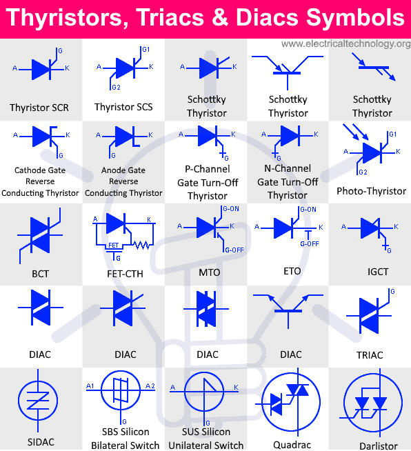
Seeing the actual symbol makes the bidirectional nature of a TRIAC easier to picture.

Real Device Comparison
Click each tab to see how these devices show up as actual part numbers in real designs.
The 2N6394 is a common general-purpose SCR rated for moderate current, used in battery chargers, DC motor control, and basic AC power switching applications where only one direction of conduction is needed.
The BT139 series is a widely used TRIAC family rated up to 600V, common in light dimmers, fan speed controls, and small motor speed regulation circuits running directly from mains AC.
The DB3 is a classic DIAC with a breakover voltage around 32V, almost always found paired with a TRIAC's gate to provide consistent, symmetrical triggering in dimmer circuits.
Gate turn-off thyristors, unlike a standard SCR, can be switched off again by a negative gate pulse rather than waiting for current zero-crossing, making them useful in high-power inverters and motor drives.
Thyristor and Triac Family Comparison Table
| Device | Terminals | Direction | Turn-Off Method | Typical Use |
|---|---|---|---|---|
| SCR | 3 (Anode, Cathode, Gate) | Unidirectional | Current below holding value | DC power control, AC rectification |
| TRIAC | 3 (MT1, MT2, Gate) | Bidirectional | Zero-crossing of AC | Light dimmers, fan and motor speed control |
| DIAC | 2 (A1, A2, no gate) | Bidirectional | Below breakover current | Triggering device for TRIACs |
| GTO | 3 (Anode, Cathode, Gate) | Unidirectional | Negative gate pulse | High-power inverters, motor drives |
Applications of Thyristors and Triacs
These six applications show where thyristors and triacs actually earn their keep in real electrical systems.
Light Dimmers
TRIACs delay firing angle each half-cycle to control lamp brightness.
Fan and Motor Speed Control
Phase-angle control adjusts average voltage delivered to small AC motors.
AC Power Switching
Solid-state relays use TRIACs to switch AC loads without moving contacts.
Battery Chargers
SCRs control rectified DC charging current with high efficiency.
Industrial Motor Drives
GTOs and SCRs handle high-power switching in variable frequency drives.
Heating Element Control
Phase-angle or zero-cross switching regulates power to resistive heaters.
Why Triacs and Thyristors Need Snubber Networks
A gate signal is not the only thing that can turn one of these devices on. A fast enough voltage transient can trigger it too, an effect known as dv/dt turn-on.
The Problem: dv/dt False Triggering
Inductive loads and switching transients can create a voltage spike that rises fast enough to falsely trigger a thyristor or triac, even with no gate signal present.
The Fix: RC Snubber Network
A resistor and capacitor wired across the main terminals slow down that rate of voltage rise, keeping it below the device's rated dv/dt limit.
Advantages and Limitations of the Thyristor Family
Why This Family Dominates Power Control
Limitations to Keep in Mind
Try It: Firing-Angle Dimmer Simulator
Drag the slider to delay the firing angle and see how much of the AC waveform actually reaches the load.
Download Thyristor and Triac References
These two resources go deeper into official thyristor and triac application design, straight from the component makers themselves.
Thyristors and Triacs: Power Semiconductor Applications
Official Philips Semiconductors application chapter on thyristor and triac design
BT139-600E TRIAC Datasheet
Real manufacturer datasheet for a widely used 600V TRIAC
Watch: Thyristor Families Explained
This video compares the SCR, TRIAC, GTO, and DIAC within the broader thyristor family.
FAQs on Thyristors and Triacs
External References
- Philips Semiconductors, Thyristors and Triacs: Power Semiconductor Applications
- Mouser Electronics, BT139-600E TRIAC Datasheet
- Electrical Technology, Thyristor, DIAC and TRIAC Symbols
- YouTube, What is Thyristor? Thyristor Families SCR TRIAC GTO DIAC Overview
What we learn today
- Thyristor is a family name covering SCR, TRIAC, DIAC, GTO, and more, all built on the same four-layer PNPN structure.
- SCRs conduct in one direction only, while TRIACs conduct in both, behaving like two SCRs in reverse-parallel.
- Once triggered, the gate loses control and the device stays latched on until current drops below the holding value.
- DIACs give TRIACs a consistent, symmetrical trigger point, while snubber networks protect against false triggering from dv/dt transients.
- Delaying the firing angle is how phase-control dimming works, and the resulting brightness change is not a straight line.