
No clock wire, no addresses, just two devices agreeing on a speed, and yet it still carries debug logs, GPS data and Modbus RTU every day.
A UART converts parallel data inside a chip into a stream of bits on a single wire and back again. It is asynchronous, so both ends must be set to the same speed and frame format before they can talk.
What Is UART Communication?
UART communication is a point to point, asynchronous serial link in which a Universal Asynchronous Receiver Transmitter sends data one bit at a time on a transmit line and receives on a separate receive line. It is the simplest form of serial communication found on almost every microcontroller.
Analog Devices points out that UART uses only two wires, Tx and Rx. There is no clock line, so both devices must use the same baud rate.

For UART communication, Tx of one device connects to Rx of the other, and grounds must be joined. Crossing these lines incorrectly is the most common beginner mistake.
The same UART hardware sits behind RS232 and RS485 ports, which only change the electrical levels. See RS232 vs RS485 differences for those layers.
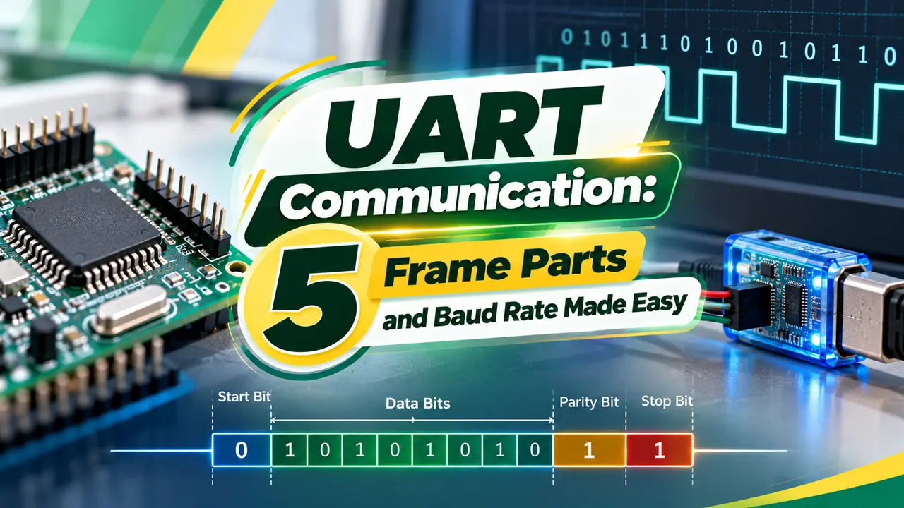
5 Frame Parts
The most common UART communication format is 8N1, meaning 8 data bits, no parity and 1 stop bit. Each byte therefore takes 10 bit times on the wire.
Analog Devices notes that the receiver samples the middle of each bit after detecting the start edge. Most UARTs oversample 16 times per bit to find that middle point.
How a Byte Travels
Inside, the transmitter is a shift register, the same building block covered in sequential circuits. A FIFO buffer lets the CPU write several bytes at once.
Because every frame resynchronises on its start bit, small clock differences do not accumulate beyond one frame. That is what makes UART communication work without a shared clock.
Baud Rate and Error Formula
Actual baud = f clock ÷ (16 × rounded divisor)
Error percent = (actual minus target) ÷ target × 100
Example, 16 MHz clock:
9600 baud: divisor 104.17, rounded 104, actual 9615, error 0.16 percent
115200 baud: divisor 8.68, rounded 9, actual 111111, error 3.5 percent
Keep total error under about 2 percent per side
A 3.5 percent error can corrupt bytes, especially if the other device also runs slightly off. That is why 14.7456 MHz crystals divide exactly into common baud rates.
Throughput with 8N1 is the baud rate divided by 10. At 115200 baud, that is about 11520 bytes per second.
Signal Levels Compared
| Standard | Logic 1 | Logic 0 | Typical Reach |
|---|---|---|---|
| TTL or CMOS UART | 3.3 V or 5 V | 0 V | Centimetres on a board |
| RS232 | Minus 3 to minus 15 V | Plus 3 to plus 15 V | About 15 m |
| RS485 | Differential A and B | Differential A and B | Up to 1200 m |
Never connect an RS232 port straight to a 3.3 V microcontroller pin, because the voltage can reach 15 V. Use a transceiver such as a MAX232, or an RS485 driver for long runs, see RS232 vs RS485 in automation.
Industrial protocols such as Modbus RTU run on top of UART frames. Parity and stop bit settings must match on every node.
Troubleshooting UART Communication
A logic analyser that decodes UART communication makes these faults obvious. Check the bit width on a scope and compare it with 1 ÷ baud.
Hardware flow control with RTS and CTS stops overruns when one side is slow. Software flow control uses special XON and XOFF characters instead.
Baud Error Calculator
Try 8 times oversampling to see the error fall for this case. Many microcontrollers offer a double speed mode for exactly this reason.
- Only two data wires.
- No clock line needed.
- Parity error checking.
- Universal support.
- Point to point only.
- Speed limited by clock accuracy.
- No built in addressing.
- Short reach at TTL levels.
TI UART Protocol PDF
UART, I2C and SPI Explained Video
UART Communication FAQ
Related Articles
- What Is Serial Communication
- RS232 vs RS485 Differences
- Modbus RTU vs Modbus TCP
- Microcontroller Working Principle
- Communication Protocols in PLC
External References
What We Learn Today
- UART communication sends framed bytes on Tx and Rx without a clock.
- Both ends must match baud rate, data bits, parity and stop bits.
- Check baud error and signal levels before blaming firmware.