How a Thermocouple Works
Heat the hot junction and warm the terminals. See why the meter reads wrong without cold junction compensation and right with it. Uses real type K data.
Quick answer: A thermocouple is two different metal wires joined at the measuring point. A temperature difference between that hot junction and the cold junction at the terminals creates a small voltage (Seebeck effect), and cold junction compensation adds back the terminal temperature.
What Is a Thermocouple?
Thermocouples are the most widely used temperature sensors in industry. They are simple, rugged, cover very high temperatures and need no power at the sensor.
The voltage they produce is small, about 41 µV per °C for type K, and it depends on the temperature difference between the hot and cold junctions. Correct extension cable and cold junction compensation are therefore essential.
Accuracy is usually ± 1.5 °C to ± 2.5 °C at moderate temperatures, so RTDs are preferred where better accuracy is needed below about 600 °C.
How a Thermocouple Works: Interactive Animation
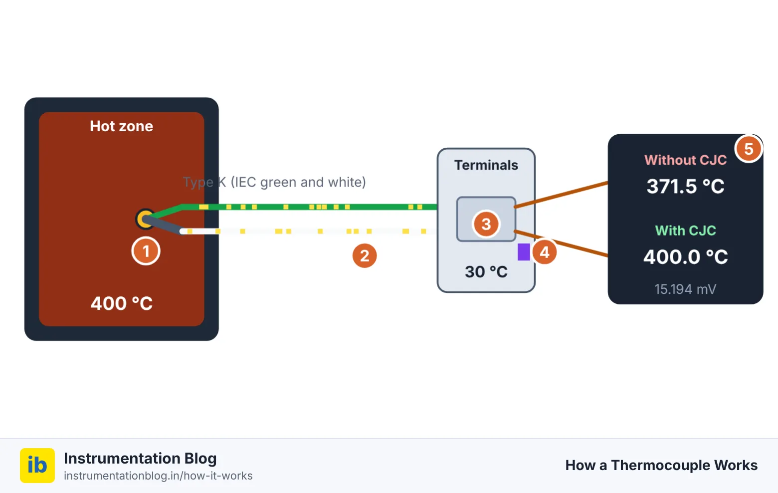
- 1Hot (measuring) junction
- 2Thermocouple wires, type K
- 3Cold junction at the terminals
- 4CJC sensor measuring terminal temperature
- 5Transmitter or meter
Thermocouple Working Principle Step by Step
- Two different alloys are welded together at the tip; for type K they are Chromel and Alumel.
- Heating one end creates a voltage along each wire, and because the alloys differ, a net voltage appears.
- The voltage depends on the difference between the hot junction and the terminals.
- The meter measures the terminal temperature with a separate sensor (CJC).
- It adds the EMF for the terminal temperature, then converts the total to temperature using the standard table.
Thermocouple Labelled Diagram
Thermocouple Formula
E(T hot) = E(measured) + E(T cold)
Example (type K): 400 °C = 16.397 mV, 30 °C = 1.203 mV
Meter sees 15.194 mV; CJC adds 1.203 mV back
Main Parts of a Thermocouple
| Part | What it does |
|---|---|
| Hot junction | Welded tip, grounded or ungrounded inside a sheath |
| Thermocouple wires | Pair of specific alloys, or matching extension cable |
| Terminals | Cold junction, where thermocouple metal meets copper |
| CJC sensor | RTD or thermistor measuring terminal temperature |
| Transmitter | Measures microvolts, applies CJC and linearisation |
Where a Thermocouple Is Used
Advantages
- Wide range, up to about 1260 °C for type K
- Rugged, small and fast responding
- Low cost and self powered
Limitations
- Small signal, sensitive to noise
- Needs correct extension cable and CJC
- Less accurate and stable than an RTD
Thermocouple Field Tips and Common Problems
- Use the correct extension or compensating cable all the way to the transmitter.
- Check polarity: reversing the wires makes the reading move the wrong way.
- Use a head mounted transmitter to keep the small mV signal away from noise.
- Replace thermocouples that have drifted after long use at high temperature.
Related Calculators and Tools
Frequently Asked Questions
Why is it called the cold junction?
It is the second junction, where the thermocouple wires connect to copper at the instrument. It is usually cooler than the measuring point.
What happens if CJC is missing?
The reading is low by roughly the terminal temperature, as the demo shows. At 30 °C terminals, the error is close to 30 °C.
Why use extension cable?
Ordinary copper wire would create a new junction at the wrong place. Extension cable keeps the same thermoelectric properties back to the terminals.
Is the mV to °C relation linear?
Not exactly. Transmitters use the standard reference tables (IEC 60584) or polynomials to convert voltage to temperature.
Learn more on the blog
Cold junction compensation in thermocouple
A practical guide on instrumentationblog.in that goes deeper into this topic with field examples.
Read Full ArticleMore How It Works
All How It Works animations · Instrumentation glossary · Comparisons