
Every transmitter, switch and valve on a P&ID carries a short code that tells you what it measures and what it does. Once you can read those letters and numbers, any loop drawing, I/O list or datasheet becomes far easier to follow.
An instrument tag such as FIC 205 packs the measured variable, the function and the loop into a few characters. This guide explains the ISA 5.1 rules, the letter tables and the numbering choices made on real projects.
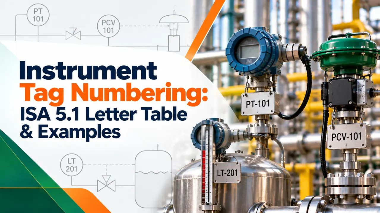
How Does Instrument Tag Numbering Work?
Instrument tag numbering gives each device a unique identity made of letters that describe the measured variable and its function, followed by a loop number shared by every device in that control loop. In FIC 205, F means flow, I means indicate, C means control and 205 is the loop, as shown on the piping and instrumentation diagram.
- The first letter is the measured or initiating variable, such as P, T, F or L.
- Succeeding letters give the function, such as I, T, C, S or V.
- The number is the loop number, shared by all devices in one loop.
- Optional prefixes show the plant area, and suffixes such as A and B separate twins.
- ISA 5.1 is the standard most plants follow.
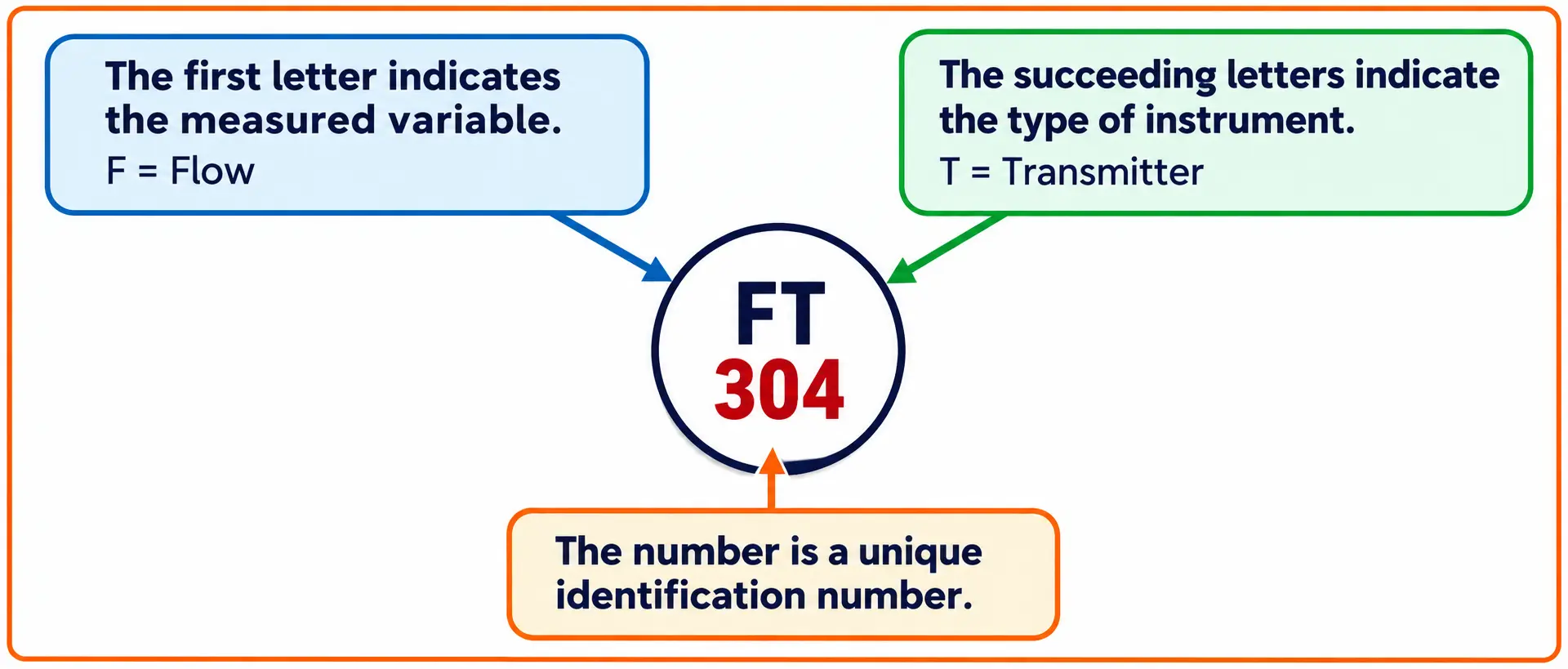
Please note that the tag FT 304 this way: F is the process variable, T is the device type and 304 is the loop number. A flow transmitter in loop 304 then sends its 4 to 20 mA signal to FIC 304 in the control room.
Control.com notes that the first letter follows the variable being measured, not the hardware. A pressure transmitter used to infer tank level is therefore tagged LT, not PT.
ISA 5.1 Identification Letters Table: First Letter
The first letter, sometimes followed by a modifier, names the measured or initiating variable. The table follows the letters listed by Control.com from ANSI/ISA 5.1, where C, G, M, N and O are left as user choice letters.
| Letter | Measured Variable | As a Modifier |
|---|---|---|
| A | Analysis, composition | None |
| B | Burner, combustion | None |
| D | User choice | Differential |
| E | Voltage | None |
| F | Flow rate | Ratio, fraction |
| H | Hand, manual | None |
| I | Current | None |
| J | Power | Scan |
| K | Time, schedule | Time rate of change |
| L | Level | None |
| P | Pressure, vacuum | None |
| Q | Quantity | Integrate, totalise |
| R | Radiation | None |
| S | Speed, frequency | Safety |
| T | Temperature | None |
| U | Multivariable | None |
| V | Vibration | None |
| W | Weight, force | None |
| X | Unclassified | X axis |
| Y | Event, state, presence | Y axis |
| Z | Position, dimension | Z axis |
A modifier changes the meaning of the first letter, so PD means pressure differential and FF means flow ratio. That is why a differential pressure transmitter is tagged PDT and never DPT in an ISA based instrument tag numbering scheme.
Succeeding Letters: Readout, Output and Modifiers
Letters after the first group describe what the device does. Control.com groups them into passive readout functions, active output functions and the H, L and M modifiers.
| Letter | Readout or Passive | Output or Active | Modifier |
|---|---|---|---|
| A | Alarm | None | None |
| C | None | Control | None |
| E | Sensor, primary element | None | None |
| G | Glass, gauge, viewing device | None | None |
| H | None | None | High |
| I | Indicate | None | None |
| K | None | Control station | None |
| L | Light | None | Low |
| M | None | None | Middle, intermediate |
| O | Orifice, restriction | None | None |
| P | Point, test connection | None | None |
| R | Record | None | None |
| S | None | Switch | None |
| T | None | Transmit | None |
| V | None | Valve, damper, louver | None |
| W | Well, probe | None | None |
| Y | None | Relay, compute, convert | None |
| Z | None | Driver, actuator | None |
Passive letters come before active ones, so a temperature recording controller is TRC and a flow indicating controller is FIC. Function modifiers come last, which is why a high high level switch reads LSHH and a high temperature alarm reads TAH.
When a letter could mean two things, its position decides. L in the first place means level, L after S or A means low, and L elsewhere can mean light, so always read the tag from left to right.
Instrument Tag Number Meaning: Worked Examples
The examples below are the tags you meet most often on Indian refinery, power and water projects. Each one follows the same instrument tag numbering logic: variable, modifier, readout, output, then function modifier.
| Tag | Meaning | Typical Device |
|---|---|---|
| PT 101 | Pressure transmitter | Gauge pressure transmitter |
| PIT 101 | Pressure indicating transmitter | Transmitter with local display |
| PDT 102 | Pressure differential transmitter | DP cell across a filter |
| FE 205 | Flow element | Orifice plate |
| FIC 205 | Flow indicating controller | DCS PID block |
| FY 205 | Flow relay or converter | I/P converter |
| FV 205 | Flow valve | Control valve in flow loop |
| TE 310 | Temperature element | RTD or thermocouple |
| TT 310 | Temperature transmitter | Head mounted transmitter |
| LSHH 401 | Level switch, high high | Trip level switch |
| PSV 520 | Pressure safety valve | Relief valve |
| ZSH 304 | Position switch, high | Valve open limit switch |
The SkillsCommons primer on P&IDs shows a complete electronic flow loop 205 built from FE, FT, FIC, FY and FV, all sharing one number. A pressure safety valve gets its own number but uses S as the safety modifier after P.
In ISA 5.1, the letter S has two jobs. As a first letter it means speed or frequency, but placed right after the first letter it becomes the safety modifier, as in PSV for a pressure safety valve.
Loop Numbers and Area Prefixes in Instrument Tag Numbering
The loop number is the numeric part of the tag, and every device in that loop shares it. Control.com describes an optional numeric prefix for the plant area, such as 12 FC 135 for unit 12, and optional suffix letters such as 135A and 135B for several identical instruments in one loop.
The SkillsCommons primer recommends no more than four letters in the alpha part and no more than four digits in the number, and says separators between the parts are optional. Projects in India commonly print the area prefix first because one plant may hold several identical units.
Each variable gets its own sequence, so FIC 101 and TIC 101 can both exist in different loops.
One sequence covers all variables, so loop 101 exists once only, whatever the letter.
A unit or area number is added in front, such as 12 PT 101.
A, B, C separate identical devices in one loop, such as PT 101A and PT 101B.
Serial instrument tag numbering keeps the DCS and SCADA tag database simple, because a loop number alone points to one loop. Parallel numbering produces shorter numbers but needs the letters every time to find the right loop.
Instrument Tag Numbering Procedure for a Project
Once tags are frozen, the marshalling cabinet terminals, cable numbers and I/O channels all follow them. Changing an instrument tag numbering decision late in a project ripples through every one of those documents.
Loop Number Planner Calculator
Capacity = 10 to the power of digits, minus 1
Solved example: area 12, 240 loops, 25 % spare
Loops needed = 240 × 1.25 = 300
Capacity with 3 digits = 999
Usage = 300 ÷ 999 × 100 = 30.0 %
Tags run from 12 PT 001 to 12 PT 300
Common Instrument Tag Numbering Mistakes
- Tagging by hardware, such as PT for a level transmitter, instead of by measured variable.
- Writing DPT instead of PDT, so the modifier sits before its letter.
- Giving each device in a loop a different loop number.
- Using a user choice letter without defining it in the P&ID legend.
- Overusing X for devices that already have a proper letter.
- Reusing a deleted loop number for a new loop.
- Leaving no spare numbers in an area.
- Mixing parallel and serial numbering in one project.
Most of these mistakes show up at loop checking when a technician cannot match a field tag with the loop drawing. Catching them in the index review costs minutes; catching them at commissioning costs days.
Keep a one page instrument tag numbering legend at the front of the P&ID set listing every user choice letter and any company rule. New engineers and contractors read it once and stop guessing.
Instrument Tag Numbering for Alarms, Switches and Safety Devices
Alarm tags combine the variable with A and a modifier, such as LAH for level alarm high and PALL for pressure alarm low low. Good alarm management under ISA 18.2 relies on these tags being consistent across the DCS and the alarm database.
Trip switches follow the same logic, so LSHH 401 is a high high level switch feeding the safety instrumented system. Limit switches on on off valves use Z, such as ZSH and ZSL, while the valve itself is often tagged with the loop variable or with H for hand.
- Any engineer can read the tag without a key.
- One number links P&ID, index, datasheet and loop drawing.
- Easy sorting and filtering in the DCS database.
- Supports audits, maintenance planning and spares.
- User choice letters differ from plant to plant.
- Company standards may add their own variations.
- Long prefixes make tag plates and HMI labels crowded.
- Renumbering after design freeze is costly.
For instrument types and the abbreviations that appear beside tags, see common automation terms and valve abbreviations. Together with the letter tables above, they cover almost every code on a typical process P&ID.
P&IDs and Symbols Primer PDF
Video on Reading ISA 5.1 Symbols
Instrument Tag Numbering FAQ
The standard is ANSI/ISA 5.1, Instrumentation Symbols and Identification, and the 2009 edition replaced the older ones. It defines the identification letters, the bubble symbols and the general rules for tag numbers.
Loop numbers themselves are assigned by the user, not by the standard. Each project therefore writes an instrument tag numbering philosophy that applies ISA 5.1 to its own plant.
Read the letters from left to right, starting with the first letter for the measured variable. Then read any modifier, the readout letters, the output letters and the function modifiers in that order.
The number that follows is the loop number. Any prefix in front shows the area, and a suffix letter separates identical devices in the same loop.
FIC stands for flow indicating controller. F is the measured variable flow, I means it indicates the value and C means it controls the loop.
In a modern plant it is usually a PID block running inside the DCS controller. It reads the flow transmitter and sends its output to the flow valve through an FY tagged converter in between.
A loop number is the numeric part of the tag, shared by every device that belongs to one control or monitoring loop. For example, FE 205, FT 205, FIC 205 and FV 205 all belong to loop 205.
The number links the P&ID, the instrument index, the datasheets and the loop drawing. Each loop number should be used for only one loop in a given area.
LSHH means level switch high high, which is a level switch set at a very high point in the vessel. L is level, S is switch and the two H letters show the high high setting.
It usually trips a pump, closes an inlet valve or shuts down the unit. A separate LSH or LAH normally gives the operator an earlier warning first.
PT is a pressure transmitter that sends a signal without a local readout listed in its tag. PIT is a pressure indicating transmitter, so the tag tells you it also has a local display.
Many smart transmitters have a display anyway, so plants differ in how strictly they apply the letter. Follow the rule set in your own tagging philosophy.
Instrument tag numbering gives every device one identity across drawings, databases and the field. Without it, technicians cannot match a transmitter on site with its loop drawing or its DCS point.
Consistent tags also speed up maintenance, spares planning, calibration records and audits. They reduce mistakes during loop checking, commissioning, shutdown work and later plant modifications.
Related Articles
- Piping and Instrumentation Diagram
- Instrument Loop Checking Procedure
- SCADA Tag Database Design
- Valve Abbreviations Explained
- Alarm Management ISA 18.2
External References
- P&IDs and Symbols Primer, SkillsCommons
- Instrument Identification Tags, Lessons in Industrial Instrumentation, Control.com
- Piping and Instrumentation Diagram, Wikipedia
What We Learn Today
- Instrument tag numbering under ISA 5.1 uses a first letter for the measured variable, succeeding letters for the function and a shared loop number.
- Modifiers follow the letter they modify, so tags read PDT, LSHH and TAH, and the first letter follows the variable rather than the hardware.
- Area prefixes, suffix letters, serial loop numbering and reserved spares keep tags unique across the index, DCS database and field tag plates.
