
Every elbow, valve and tee upstream of a meter twists and skews the flow before it reaches the sensor. Knowing how much straight pipe you need, and when a conditioning device can shorten it, saves space and protects accuracy.
Most flow meters are calibrated with a smooth, symmetrical velocity profile that rarely exists in a crowded plant. Straight pipe and a well chosen flow conditioner bring the real installation closer to those laboratory conditions.
What Is a Flow Conditioner?
A flow conditioner is a device installed upstream of a flow meter that removes swirl and reshapes a distorted velocity profile into a stable, fully developed one. It tackles one of the key factors affecting flow meter readings, the piping layout.
Every meter in our guide to types of flow meters assumes a certain profile. Elbows, pumps and partly open valves break it.
Primary Flow Signal states that a correctly selected flow conditioner can eliminate up to 80 to 90 percent of pipeline swirl. Its units cover line sizes from 2 to 48 inches and follow ISO 5167, ASME PTC 6, AGA 3 and API 14.3.
How Swirl and Profile Distortion Upset a Meter
In fully developed turbulent flow the velocity is highest at the centre and falls smoothly towards the wall. The exact shape depends on the Reynolds number.
Two elbows in different planes create swirl that can persist for 50 or more diameters. An orifice plate responds strongly, because its discharge coefficient shifts when the profile is skewed.
Common Flow Conditioner Designs
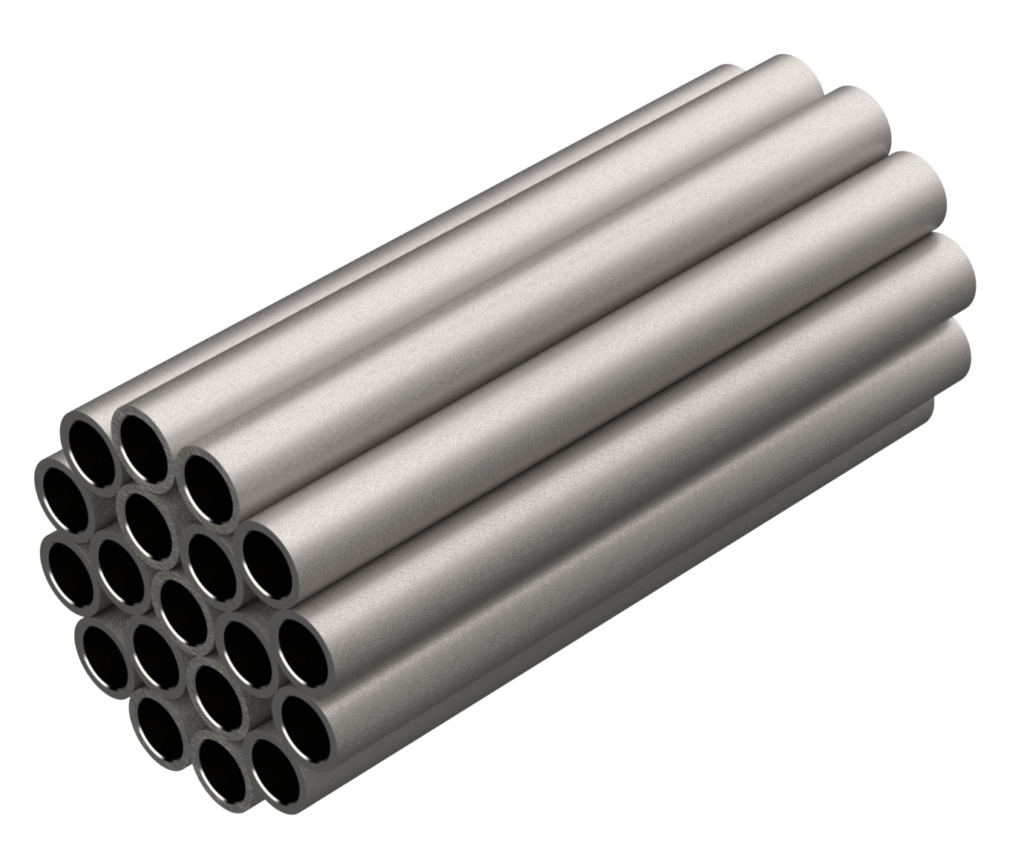
Parallel tubes that mainly remove swirl.
A thick plate with a designed hole pattern.
Radial vanes in a short spool.
Four holes acting as element and conditioner.
Cherokee Tulsa explains that flow leaving a perforated plate is swirl free and becomes fully developed after about 5 to 8 pipe diameters. The same source warns that a tube bundle facing swirl may need a 30 D to 40 D meter run.
The four hole plate combines element and flow conditioner in one piece. Compare it in conditioning orifice plate vs standard orifice plate.
Straight Run Requirements by Meter Type
| Meter Type | Upstream | Downstream |
|---|---|---|
| Orifice plate | 10 D to over 40 D | 4 D to 8 D |
| Orifice with flow conditioner | About 17 D total run | Included |
| Magnetic | About 5 D | About 2 D |
| Ultrasonic | 10 D to 20 D | About 5 D |
| Vortex | 15 D to 20 D | About 5 D |
| Coriolis | Usually none | Usually none |
These are typical starting points, since each maker publishes its own table. Magmeter guidance is in magnetic flow meter sizing and installation.
Vortex meters need long runs because shedding depends on a clean profile, as shown in vortex flow meter working principle. Ultrasonic needs vary with path count, see how an ultrasonic flow meter works.
What ISO 5167 and AGA 3 Say
ISO 5167 Part 2 tabulates upstream lengths for orifice plates by fitting and beta ratio. It also sets a test so a flow conditioner can be approved for shorter runs.
AGA Report 3, also published as API 14.3, covers gas orifice metering. Klaus Zanker and Dale Goodson of Daniel Industries reported a 17 D meter tube, with the flow conditioner 7.5 D upstream of the plate, that passed every API 14.3 test for beta up to 0.67.
Check beta ratio in your orifice plate sizing before choosing the run length. A smaller beta tolerates disturbance better.
7 Proven Flow Conditioner Installation Tips
Stable readings also depend on the points in flow meter reading stability factors. Insertion meters sample one point, so they are even more profile sensitive, see insertion vs full bore flow meters.
Straight Length Formula
Downstream length = Pipe ID × Downstream D multiple
Example, 200 mm vortex meter:
Upstream 10 D = 0.2 m × 10 = 2.00 m
Downstream 5 D = 0.2 m × 5 = 1.00 m
Total straight run = 3.00 m
Straight Run Length Calculator
Use the actual inside diameter, not the nominal size. If the answer does not fit your pipe rack, a flow conditioner or a less sensitive meter is the fix.
- Shortens straight pipe needed.
- Removes swirl.
- Improves repeatability.
- Recognised in standards.
- Adds pressure loss.
- Can foul in dirty service.
- Needs tested spacing.
- Adds a spool to maintain.
API 14.3 Qualification Paper PDF
Perforated Plate Conditioning Video
Flow Conditioner FAQ
It removes swirl and reshapes a distorted velocity profile ahead of a flow meter. The meter then sees flow that is close to the conditions used during its calibration.
This reduces the length of straight pipe needed upstream of the meter. It is most useful on orifice, vortex, turbine and ultrasonic meters installed in crowded piping.
No, a tube bundle mainly kills swirl and does little to rebuild the velocity profile. A perforated plate does both jobs with a carefully designed hole pattern.
Tube bundles can need very long meter runs when upstream swirl is strong. A perforated plate flow conditioner usually settles the flow within about 5 to 8 pipe diameters.
It depends on the upstream fitting and the beta ratio listed in ISO 5167 Part 2. Figures range from about 10 D to more than 40 D upstream.
Downstream needs are shorter, typically 4 D to 8 D after the plate. An approved conditioning device can cut the total meter run to around 17 D in many gas stations.
Yes, but much less than most other meters, commonly about 5 D upstream and 2 D downstream. Always follow the specific manufacturer table for your model and size.
Partly filled pipes and trapped air usually cause much bigger errors than profile distortion. Keep the tube full and mount the electrodes on a horizontal axis.
Shedding frequency depends on a clean, symmetrical profile across the bluff body. Swirl and skew change that frequency and shift the calibrated K factor.
Typical runs are 15 D to 20 D upstream and about 5 D downstream. A control valve installed upstream of the meter can demand far longer lengths, sometimes 50 D.
It is higher than a tube bundle and roughly similar to a low beta orifice restriction. Suppliers publish a loss coefficient for each plate design and size.
Check the loss at maximum flow in your pump or compressor calculation. In low pressure gas systems this loss may decide which design you finally choose for the line.
ISO 5167 Part 2 includes a compliance test for devices used ahead of orifice plates. AGA Report 3, also known as API 14.3, covers gas orifice meter tubes.
Both standards allow shorter runs when the device passes the tests. Keep the tested spacing and orientation in the field, or the approval no longer applies to your installation.
Related Articles
- Orifice Plate Flow Measurement
- Conditioning Orifice Plate and Standard Orifice Plate
- Vortex Flow Meter Working Principle
- Magnetic Flow Meter Sizing and Installation
- Flow Meter Readings Stability Factors
External References
- Qualification of a Flow Conditioning Device to API 14.3, IMEKO
- Flow Conditioning for Flow Meter Accuracy, Cherokee Tulsa
- Flow Conditioning, Wikipedia
What We Learn Today
- A flow conditioner removes swirl and rebuilds a fully developed velocity profile, so the meter reads almost exactly as it did during calibration.
- Straight run needs vary widely, from about 5 D for magmeters to more than 40 D for high beta orifice plates after elbows.
- Perforated plates recover the profile within about 5 to 8 diameters, while simple tube bundles mainly remove swirl and need longer runs.