
Fast IGBT edges travelling down a long motor cable can double the voltage at the motor terminals and quietly destroy insulation.
Modern drives switch in a fraction of a microsecond, and long cables turn those steep edges into voltage spikes at the motor. Output filters slow the edges and keep peaks inside the insulation rating.
What Is a DV DT Filter?
A DV DT filter is an output filter installed between a VFD and its motor that slows the rise time of each PWM pulse and limits the peak voltage at the motor terminals. It normally combines series inductors with a damped RC network, and it protects motors fed through long cables from a VFD.
The term dv/dt means the rate of change of voltage, measured in volts per microsecond. The faster the edge, the higher the stress on the first turns of the motor winding.
The IGBTs inside a drive switch in roughly 50 to 400 ns. That speed keeps drive losses low but makes the cable behave like a transmission line.
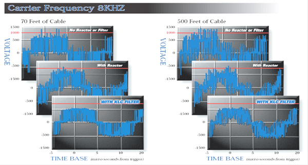
VFDs.com notes that both peak voltage and dV/dt must stay within limits, with about 1000 V per µs used as a guideline on 480 V systems. Overshoot grows with cable length and switching frequency.
How Reflected Wave Voltage Forms
On a 480 V drive the DC bus is about 650 V, so the reflected peak can exceed 1300 V. Ringing and double pulsing can push it higher.
Standard motors with basic insulation may fail between turns long before the thermal class limit is reached. Partial discharge slowly erodes the enamel.
Critical Cable Length and dv/dt
dv/dt ≈ Peak voltage ÷ Rise time
v = wave speed in the cable, about 150 m per µs, tr = rise time
Worked example, 480 V drive:
tr = 0.1 µs, lc = 150 × 0.1 ÷ 2 = 7.5 m
Without filter: 1300 V ÷ 0.1 µs = 13000 V per µs
A filter that stretches tr to 1.3 µs brings dv/dt near 1000 V per µs
Beyond the critical length the full reflection develops, so even a modest run of 20 m can double the voltage. Faster devices mean shorter critical lengths.
NEMA MG1 Part 31 inverter duty motors withstand about 1600 V peak with rise times of 0.1 µs or longer. Older motors often cannot.
5 Smart dv/dt Filter Rules
VFDs.com reports that a dv/dt filter keeps spikes below 1000 V and reduces dV/dt about three times. That is usually enough for 480 V motors on medium runs.
Keep motor cables shielded and bonded at both ends to control noise, as described in shielded and twisted pair cables.
Output Filter Types Compared
Series inductor that slightly slows edges.
Inductor with damped RC network.
LC filter giving a near sinusoidal output.
RC network mounted at the motor.
A sine wave filter gives the cleanest output but costs more and creates a larger voltage drop. It also limits the maximum drive switching frequency.
Filters also reduce EMI and audible motor noise. They do not fully stop common mode bearing currents, which need grounding brushes or insulated bearings.
Signs You Need Output Filtering
Cable charging current on long runs can cause VFD overload trips. A filter reduces the capacitive current pulses at each edge.
Critical Length Calculator
Compare the peak with the motor withstand rating and the dv/dt with 1000 V per µs. If either is exceeded, specify a dv/dt filter or better.
- Protects motor insulation.
- Allows longer cable runs.
- Reduces EMI and noise.
- Extends motor life.
- Extra heat and voltage drop.
- Limits carrier frequency.
- Adds cost and panel space.
- Little help for bearing currents.
Eaton Output Filters PDF
VFD Waveforms With Filter Video
dv/dt Filter FAQ
Related Articles
- VFD Working Principle
- VFD Parameter Configuration
- Power Quality Issues With VFDs
- Motor Insulation Classes
- Cable Sizing for Motor Feeders
External References
- Output Filters and Motor Lead Length, Eaton
- Voltage Spike and Motor Protection, VFDs.com
- Variable Frequency Drive, Wikipedia
What We Learn Today
- Fast edges on long cables reflect and can double motor voltage.
- Critical length depends on rise time and cable wave speed.
- Choose a reactor, dv/dt filter or sine filter by cable length and motor rating.