
A breaker can only protect people if enough fault current flows to trip it fast, and the loop impedance decides that current.
When a live conductor touches earthed metal, fault current flows around a loop through the supply, the fault and the earth path. The lower the impedance of this loop, the faster the protective device trips.
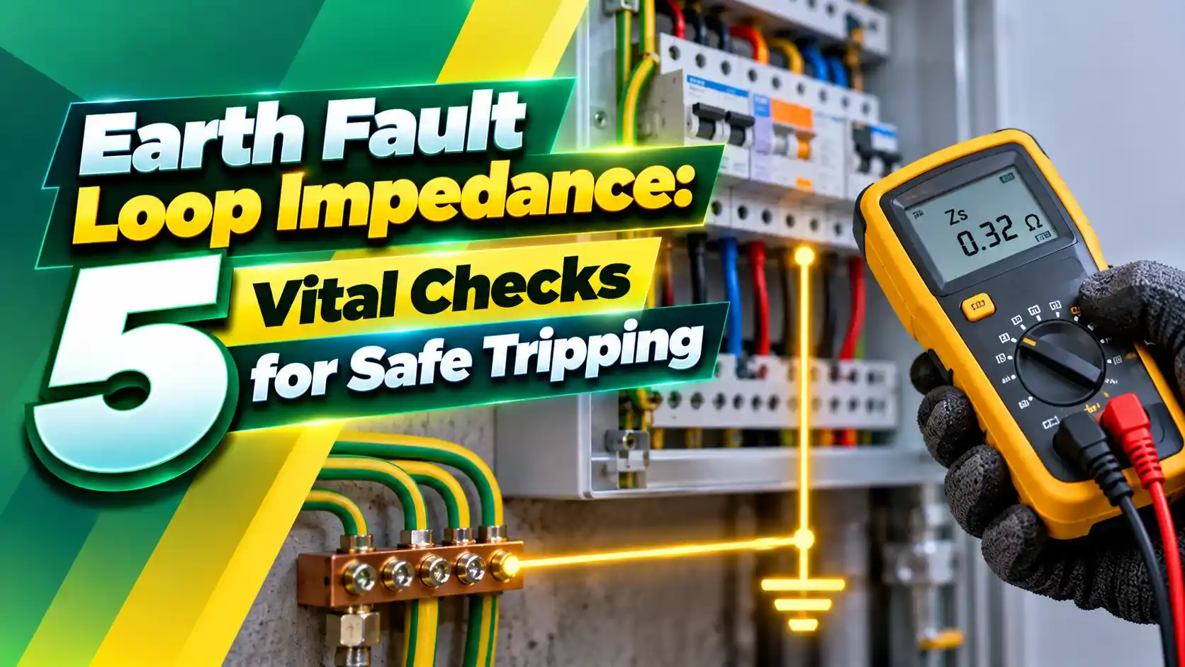
What Is Earth Fault Loop Impedance?
Earth fault loop impedance is the total impedance of the path that fault current takes from the point of fault, through the protective conductor and earth return, back through the supply transformer and the line conductor. It is measured in ohms and written as Zs for a complete circuit.
The path depends on the earthing arrangement, explained in our TN, TT and IT earthing systems guide. In TN systems the return is metallic, so the loop is low and breakers can clear faults.
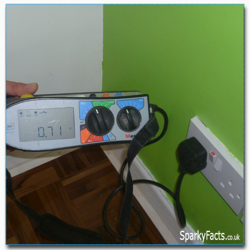
Megger explains that the test proves enough fault current will flow to operate the protective device within the BS 7671 disconnection time. If the loop is too high, exposed metal can stay live at a dangerous touch voltage.
Two values matter. Ze is the external loop outside the installation, and Zs is the whole loop seen at the far end of a circuit.
Ze, Zs and the Loop Formula
Fault current If = (Cmin × U0) ÷ Zs
Max Zs = (Cmin × U0) ÷ Ia
R1 = line conductor resistance, R2 = protective conductor resistance, Cmin = 0.95, U0 = 230 V, Ia = current for instant trip
Worked example, Type B 32 A MCB:
Ia = 5 × 32 = 160 A
Max Zs = 0.95 × 230 ÷ 160 = 1.37 Ω
Ze = 0.35 Ω, R1 + R2 = 0.52 Ω, Zs = 0.87 Ω
If ≈ 251 A, well above 160 A, so the breaker trips instantly
Typical declared Ze values are 0.35 Ω for TN C S supplies and 0.8 Ω for TN S supplies. Always measure the real value on site rather than relying on the declared one.
The same loop decides the prospective fault current, which links this test to short circuit fault current calculations.
5 Vital Checks for Safe Disconnection
The 80 percent rule allows for conductor temperature rise during a fault, which increases resistance. A cold measurement of 1.37 Ω would fail, while 1.10 Ω or less passes for a Type B 32 A breaker.
Record every reading on the schedule of test results, including the device type and rating. This makes periodic inspection much faster.
Maximum Zs by Breaker Curve
| Device | Instant Trip Current | Max Zs, 32 A | 80 Percent Value |
|---|---|---|---|
| Type B MCB | 5 × In | 1.37 Ω | 1.10 Ω |
| Type C MCB | 10 × In | 0.68 Ω | 0.55 Ω |
| Type D MCB | 20 × In | 0.34 Ω | 0.27 Ω |
Type C and D curves need much lower loop values, which is why they suit motor circuits with short cable runs. Our MCB vs MCCB vs ELCB vs RCCB guide compares device choices.
Selecting the right rating comes first, as covered in MCB rating calculation. Coordination between devices is explained in breaker time current curves.
Test Methods and Safety
Megger warns that no trip test modes can read slightly high, an effect known as RCD uplift. Where readings are close to the limit, repeat the test or use the calculated value.
Live testing exposes the tester to shock and arc hazards, so follow NFPA 70E electrical safety practice and wear suitable PPE.
How to Lower a High Loop Reading
Protective conductor sizing is covered in the earth conductor size calculation article. Longer circuits also need a voltage drop calculation.
Breaker Check Calculator
This check covers 230 V TN circuits with 0.4 second disconnection. Always confirm against the tables in the current edition of BS 7671.
- Measure, do not assume Ze.
- Apply the 80 percent rule.
- Record device type with each reading.
- Retest after any alteration.
- Leaving the main earth disconnected.
- Ignoring RCD uplift.
- Using Type C tables for Type B devices.
- Testing without safe isolation.
Electrotechnik Loop Impedance PDF
Loop Testing Explained Video
Loop Impedance FAQ
Related Articles
- TN, TT and IT Earthing Systems
- MCB vs MCCB vs ELCB vs RCCB
- Calculate Short Circuit Fault Current
- Earth Conductor Size Calculation
- Electrical Regulations and Standards
External References
- Understanding Loop Impedance, Electrotechnik
- Loop Impedance Testing, Megger
- Earthing System, Wikipedia
What We Learn Today
- Zs equals Ze plus the circuit R1 + R2 and sets the fault current.
- Compare measured Zs with 80 percent of the BS 7671 table value.
- Test safely and fix high readings before energising.