
Trip faster for big faults and slower for small overloads, the simple idea behind selective overcurrent protection.
An IDMT relay trips in a time that falls as fault current rises, but never faster than a definite minimum. This inverse behaviour lets several relays in series grade with each other so only the nearest breaker opens.
What Is an IDMT Relay?
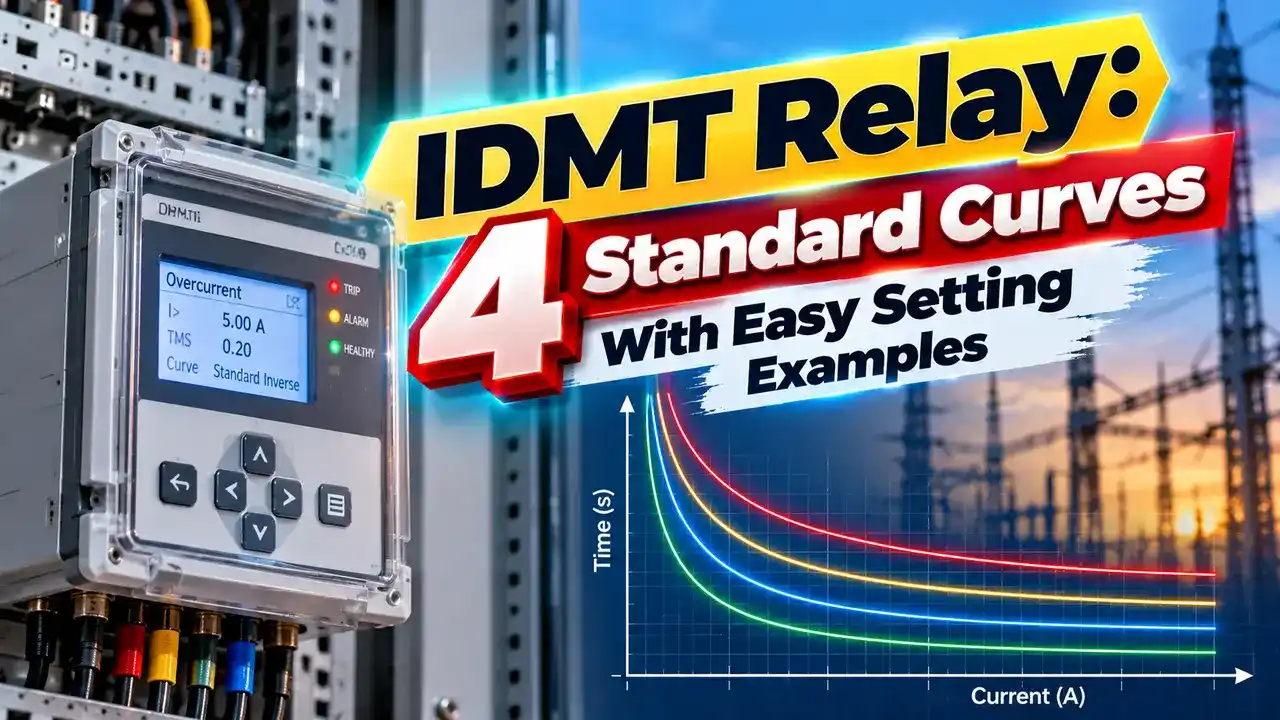
An IDMT relay, short for inverse definite minimum time, is an overcurrent relay whose operating time decreases as current increases. It is one of the most common protective relays on feeders, transformers and motors.
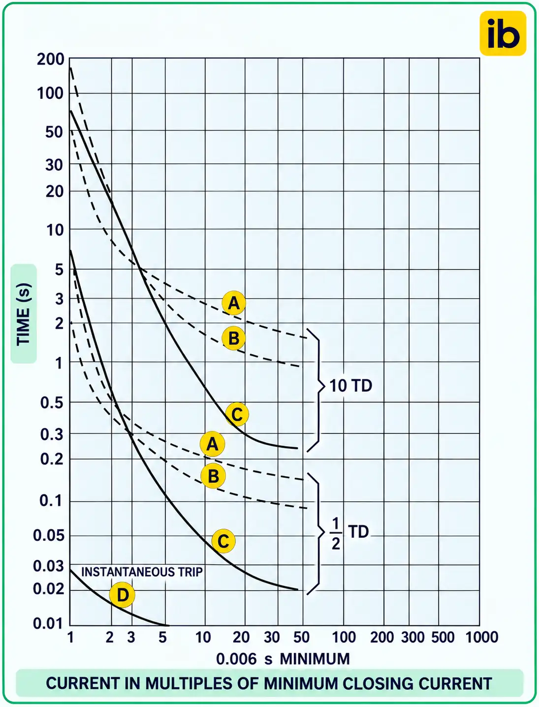
At currents just above the pickup setting, the relay waits a long time, allowing for temporary overloads. At high fault currents, it trips quickly, but the curve flattens to a definite minimum time.
The relay receives current through a current transformer, usually with a 1 A or 5 A secondary. Modern numerical relays calculate the curve digitally from IEC or IEEE equations.
Older electromechanical relays used an induction disc whose speed rose with current. The same curve shapes are kept today for compatibility with existing grading studies.
PSM and TMS Explained
The plug setting multiplier, PSM, tells how many times the fault current exceeds the pickup. For a 400/1 CT with 100 percent plug setting, pickup is 400 A, so a 4000 A fault gives a PSM of 10.
The time multiplier setting, TMS, slides the whole curve up or down in time without changing its shape. It is the main tool for grading relays against each other.
4 Standard IEC Curves
Very inverse suits systems where fault current depends strongly on fault location. Extremely inverse matches fuse curves closely, which helps when a relay backs up downstream fuses.
IEEE curves such as moderately, very and extremely inverse follow similar ideas with different constants. Use the same family for every relay in one grading chain.
IDMT Relay Trip Time Formula
Standard inverse: k = 0.14, α = 0.02
Very inverse: k = 13.5, α = 1
Extremely inverse: k = 80, α = 2
Worked example, standard inverse:
CT 400/1, plug 100 percent, fault 4000 A, so PSM = 10
10^0.02 = 1.0471
t = 0.1 × 0.14 ÷ (1.0471 minus 1) = 0.1 × 2.97
t ≈ 0.30 s at TMS 0.1
Very inverse gives 0.15 s, extremely inverse 0.081 s
The same fault gives very different times on each curve. That is why curve choice matters as much as the numeric settings.
Fault currents for PSM come from short circuit current calculation at each relay location, for both maximum and minimum conditions.
Grading Relays in Series
For selectivity, the upstream relay must be slower than the downstream relay at every fault level by a grading margin. A margin of about 0.3 to 0.4 s is common with numerical relays and modern breakers.
The margin covers breaker operating time, relay overshoot and CT errors. Too small a margin risks both relays tripping, and too large makes upstream clearing unnecessarily slow.
Plotting all curves on one log log chart is the classic method, explained in time current curve coordination. Software now does the plotting, but engineers must still check the result.
Curve Comparison at PSM 10
| Curve | k | α | Time at PSM 10, TMS 0.1 |
|---|---|---|---|
| Standard inverse | 0.14 | 0.02 | About 0.30 s |
| Very inverse | 13.5 | 1 | 0.15 s |
| Extremely inverse | 80 | 2 | About 0.081 s |
| Long time inverse | 120 | 1 | About 1.33 s |
At lower PSM values the differences grow even larger. Extremely inverse becomes very slow for small overloads, which helps ride through motor starting currents.
For motors, the IDMT relay often works alongside dedicated functions described in motor protection relay types.
Where IDMT Protection Is Used
Earth fault elements use the same equations with lower pickup settings. The residual CT connection sums the three phases to detect earth current.
Relay settings are only as good as the CT circuit, so never leave a secondary open, as warned in CT secondary open circuit risks.
IDMT Trip Time Calculator
Change k and α to compare curves for the same fault. Then adjust TMS until the grading margin with the downstream relay is met.
- Fast clearing of heavy faults.
- Tolerates short overloads.
- Easy grading between relays.
- Standard, well understood curves.
- Slower for faults far from the source.
- Grading gets slow near the source.
- Depends on accurate fault studies.
- Needs CT performance checks.
IDMT Relay Curve Guide
PS and TMS Explained on Video
IDMT Relay FAQ
Related Articles
- Protective Relays Explained
- Circuit Breaker Coordination
- Current Transformer Working Principle
- Short Circuit Current Calculation
- Motor Protection Relay Types
External References
- IDMT Relay Curve Guide, European Arc Guide
- Types of Overcurrent Relay, EEP
- Relay Settings in Real Power Systems, Allumiax
- Protective Relay, Wikipedia
What We Learn Today
- Inverse curves trip faster for larger currents, with a definite minimum time.
- PSM sets where on the curve the fault lands, TMS shifts the curve in time.
- Grading margins of about 0.3 to 0.4 s keep protection selective.