
A fail-safe valve position is the position a control valve moves to when it loses its control signal, instrument air, or actuator power.
This is a deliberate engineering decision — not a default. It is based on what is safest for the process and personnel when something goes wrong.
Selecting the wrong fail-safe valve position is a process safety error.
It cannot be corrected in the field without changing the actuator spring or valve action, a significant rework requiring a management of change.
The fail safe valve position is determined by the process hazard, not by instrumentation convenience.
A cooling water valve should fail open. A fuel gas valve should fail closed. A fail-safe valve positioned incorrectly makes the process less safe when the instrument fails.
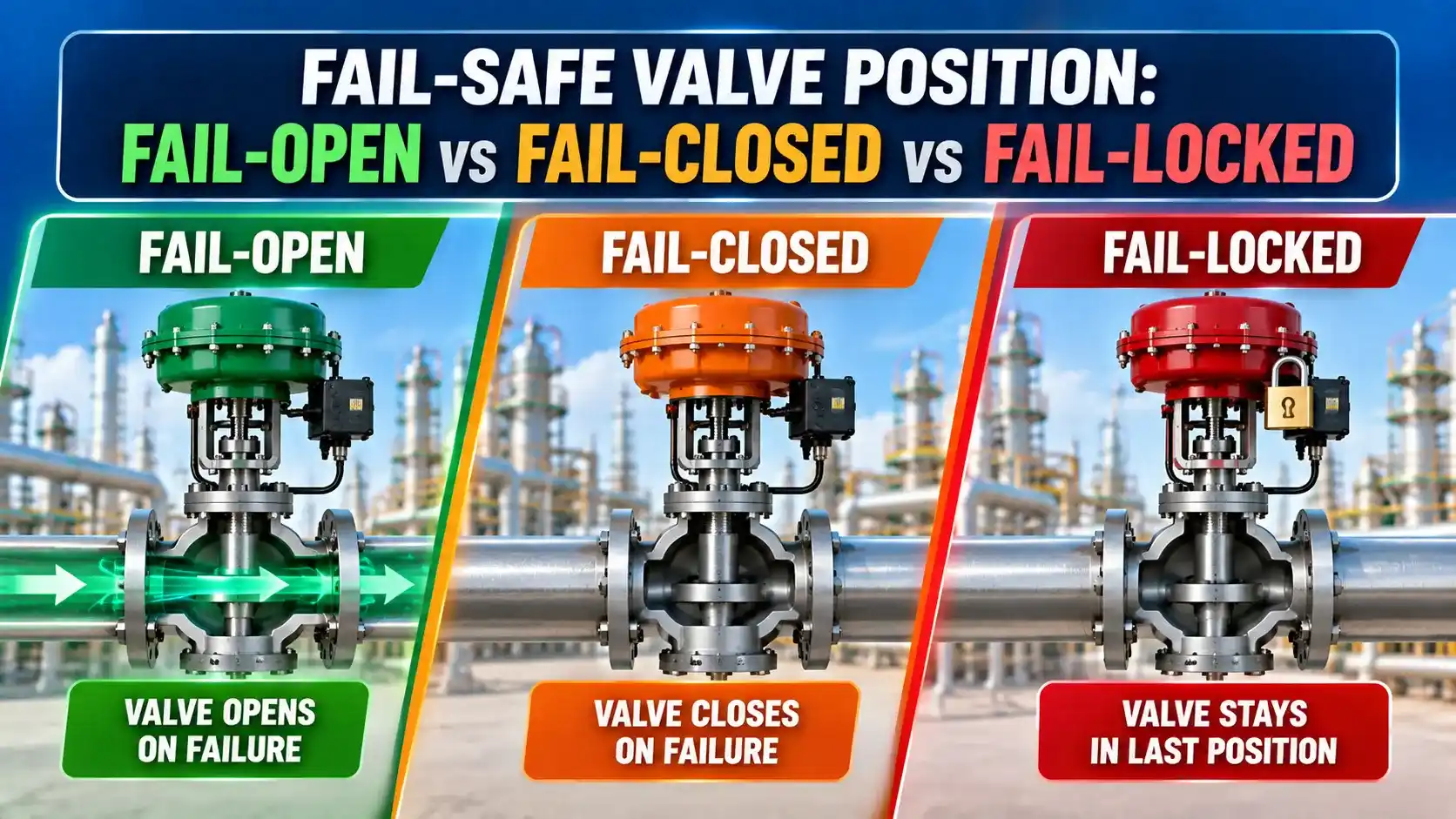
What Is a Fail Safe Valve Position?
A control valve actuator has a preferred direction of travel when air or electrical signal is lost.
For a pneumatic spring-return actuator, the spring pushes the valve to its fail safe position.
For an electric actuator, the position is set by a spring return or a battery-backed drive that moves the valve on power loss. This is the fail-safe valve position.
An ATC actuator closes the valve when air pressure is applied (and opens when air is lost). So an ATC valve is fail-open.
An ATO actuator opens the valve when air pressure is applied (and closes when air is lost). So an ATO valve is fail-closed.
On a P&ID, the fail-safe position is shown by the valve symbol: FC (fail closed), FO (fail open), or FL (fail locked). These annotations are definitive. The ATC/ATO notation describes the actuator mechanism that achieves that position.
The Three Fail Safe Valve Positions Explained
A fail-open valve moves to the fully open position when the control signal, instrument air, or actuator power is lost.
The spring in a spring-return pneumatic actuator pushes the valve open. The valve closes against this spring force during normal operation.
This is an ATC (Air-To-Close) actuator. Increasing air pressure closes the valve. Removing air pressure allows the spring to open it.
When to use fail-open: Any service where continued flow is safer than stopping flow on instrument failure.
Classic fail-open services: cooling water lines, steam heating on freeze-sensitive pipelines, and feed valves where stopping flow is more hazardous than continued flow.
If the instrument air supply fails, the valve opens fully — providing maximum cooling to protect the process from overtemperature.
The alternative (fail-closed on a cooling water line) would stop cooling on instrument failure, allowing the process temperature to rise unchecked — exactly the scenario the cooling system was designed to prevent.
For high-pressure valves, the spring force needed to open the valve against line pressure can be very large — requiring a large-bore actuator cylinder.
This is why fail-open high-pressure valves are often bigger and heavier than the equivalent fail-closed valve at the same pipe size and Cv. The spring has to do more work.
A fail-closed valve moves to the fully closed position on loss of control signal, instrument air, or actuator power.
The spring pushes the valve closed. The valve opens against this spring force during normal operation.
This is an ATO (Air-To-Open) actuator. Increasing air pressure opens the valve. Removing air pressure allows the spring to close it.
When to use fail-closed: Any service where stopping flow is safer than allowing uncontrolled flow on instrument failure.
Classic fail-closed services: fuel gas valves (stop fuel on loss of control), chemical injection valves, and high-pressure letdown valves that must close to prevent downstream overpressure.
If the flame goes out and the fuel control valve fails open, unburned gas accumulates in the firebox — creating an explosion hazard.
The fail-closed position shuts off fuel on loss of signal, giving the flame safeguard system time to respond. See the process control valves guide and the valve selection guide for how this integrates into burner management.
A valve that is fail-closed by design but whose spring has relaxed, whose actuator seals have hardened, or whose plug is stuck on sediment may not close when commanded.
IEC 61511 (see the control valve troubleshooting guide) requires periodic proof testing of all SIS final elements, including the full stroke test (or partial stroke test with statistical adjustment) of each fail-safe valve in the safety instrumented function.
A fail-locked valve stays at whatever position it held at the moment of signal loss.
It is neither fully open nor fully closed. It locks at its last position, also called fail-last or fail-in-place.
This is not achieved by a spring. A lock-up relay on the actuator air supply traps the air already in the cylinder when instrument air pressure drops below a threshold.
The trapped air holds the valve at its current position until the air supply is restored.
When to use fail-locked: Processes where both full-open and full-closed positions are unacceptable on failure. Moving to either extreme would cause more harm than staying at the current position.
Classic fail-locked services: large pipeline isolation valves (water hammer risk), temperature-critical processes where a sudden flow step damages equipment, and ratio control valves where an abrupt position change upsets the blend.
A lock-up relay can leak slowly over time, allowing the valve to drift from its last position after a long instrument air outage. This means a fail-locked valve is not a reliable safety function — it is a process continuity function.
For SIS applications, only fail-open or fail-closed positions are acceptable for the safety function. Fail-locked valves may be used for the regulatory control layer but must never be the SIS final element.
On a P&ID, it may be annotated as FL, FLP (fail-last position), or FI (fail-in-place), depending on the company's documentation standard.
Always verify which abbreviation your project's P&ID legend uses before interpreting valve failure annotations. FL on one company's P&ID means fail-locked; on another's it may mean fail-low (fail to minimum position) — a completely different action.
How the Actuator Achieves Each Fail Safe Position
The fail-safe position is determined by the actuator type and its spring arrangement not by the valve body or trim alone.
| Actuator Type | Fail-Open (FO) | Fail-Closed (FC) | Fail-Locked (FL) |
|---|---|---|---|
| Pneumatic spring-return diaphragm | Spring extends stem upward, opening valve (direct-acting body) or closing plug on seat (reverse action). Air pressure opposes spring. | Spring pushes stem downward, seating plug. Air pressure lifts plug against spring. | Not applicable — spring always drives valve to one end. Fail-locked requires a lock-up relay added to the air supply line. |
| Pneumatic piston actuator | Spring on one side of piston drives stem to open position. Double-acting variant uses a separate compressed air reservoir. | Spring on other side of piston drives stem to closed. Air pressure to the cylinder opposes spring during normal operation. | Lock-up relay traps air on both sides of piston on air supply loss. Valve holds last position. |
| Electric actuator (EIM, Auma, Rotork) | Battery-backed motor drives to full open on power loss. Or spring-return mechanism within the actuator body. | Battery-backed motor drives to full close on power loss. Spring-return option also available. | Motor de-energises on power loss; mechanical brake holds last position. No battery needed. |
| Solenoid valve (on-off safety function) | Normally open (NO) solenoid — spring holds open, energised to close. De-energises to open on power loss. | Normally closed (NC) solenoid — spring holds closed, energised to open. De-energises to close on power loss. | Latching solenoid — maintains last position without power. Not commonly used in SIS applications. |
Fail-Safe Valve Position Selector Tool
Watch: Fail-Open, Fail-Closed and Fail-Lock Control Valve Explained
Fail Safe Valve Position Questions
External References
- Valve Actuator Selection: Fail-Safe Action and Spring Return Design | Emerson Fisher
- ISA-5.1: Instrumentation Symbols and Identification — FC, FO, FL Notation | ISA
What We Learn Today
- FC (fail-closed) uses an ATO actuator: spring closes the valve on air loss. FO (fail-open) uses an ATC actuator: spring opens the valve on air loss. FL (fail-locked) uses a lock-up relay to trap air and hold the last position.
- The fail-safe position is determined by process hazard analysis, not by instrumentation convenience. A cooling water valve is FO. A fuel gas valve is FC. Both positions have specific safety reasons behind them.
- Fail-locked valves are a process continuity choice, not a safety choice. They must never be the final element in a Safety Instrumented System (SIS) — IEC 61511 requires a defined safe position (open or closed).