
DCS PID auto tune is the process by which a DCS automatically determines optimal PID gains without requiring manual trial-and-error tuning of Kp, Ti, and Td.
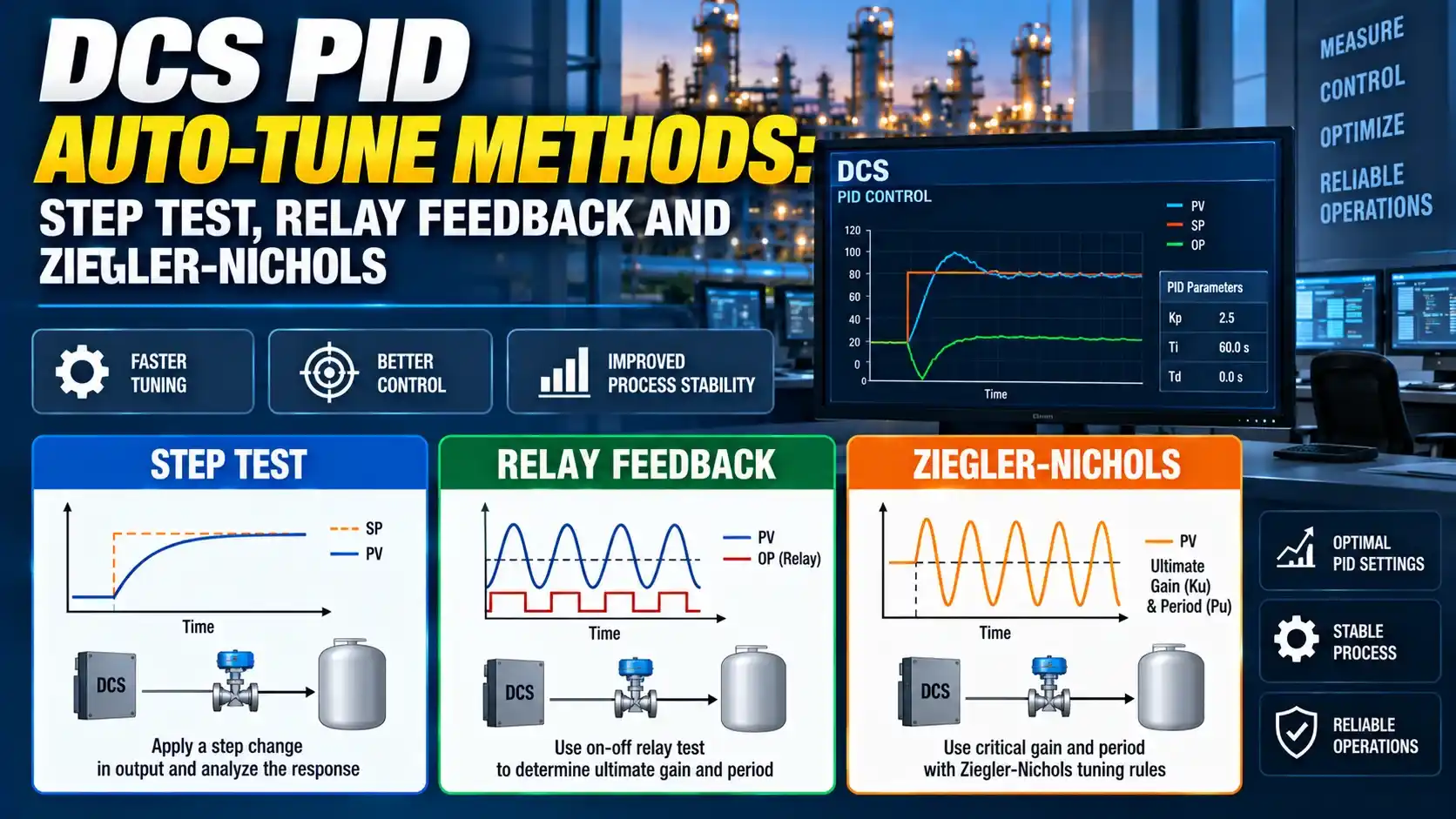
Three methods are used in practice: the open-loop step test, the relay feedback test, and the Ziegler-Nichols closed-loop oscillation method.
This guide covers how each DCS PID auto-tune method works, when to use it, and includes a calculator to compute PID parameters from step test results.
The relay feedback method is the most widely implemented DCS PID auto tune technique today. It produces a controlled limit cycle rather than pushing the loop toward instability.
The step test remains the most transparent method every engineer can see and verify the process model directly from the step response data.
Why DCS PID Auto-Tune Exists
Manual PID tuning requires the engineer to apply a bump test, measure the process response, and calculate Kp, Ti, and Td from the step response shape.
DCS PID auto tune automates this identification step. The DCS makes a controlled disturbance, measures the process response, fits a process model, and calculates PID gains.
The engineer's job is then to verify the model and accept or adjust the computed gains.
John G. Ziegler and Nathaniel B. Nichols developed two methods: an open-loop step test method using the process reaction curve, and a closed-loop oscillation method using the ultimate gain and ultimate period. Both are still used today, though DCS platforms typically implement the relay feedback variant of the closed-loop method rather than the original "push to oscillation" approach.
The original Ziegler-Nichols rules were designed for good disturbance rejection, which often means aggressive tuning with significant overshoot. Modern DCS auto-tune implementations typically use a modified version targeting a better balance between setpoint tracking and disturbance rejection.
The Three DCS PID Auto Tune Methods Explained
How it works: The controller switches to manual. The DCS applies a step change (typically 5 to 10% of output) and records the PV response until it reaches steady state.
From the response curve, the DCS fits a FOPDT model: gain K, dead time L (delay before PV moves), and time constant T (time to 63.2% of the final PV change).
Together these three values define the process fully enough for the DCS to calculate initial PID gains.
Tuning calculation: The DCS applies a tuning rule to K, L, and T to compute Kp, Ti, and Td.
The IMC rule with an adjustable lambda is most common in modern DCS. It lets engineers trade off loop speed against robustness.
Best for: Temperature loops, slow pressure loops, and flow loops with dominant dead time where taking the loop to manual is safe. Self-regulating processes with clean step responses.
Too small a step (below 3%) produces a PV response buried in noise. The process model will be inaccurate and the computed PID gains will be wrong.
Too large a step (above 15%) drives the PV into a nonlinear region and the identified model will not represent the loop's normal operating behaviour.
Use 5 to 10% of the output range for most loops. For highly nonlinear processes (pH loops, reactor temperature near exothermic transition), use 3 to 5% and conduct the step test at the normal operating point, not at startup or shutdown conditions.
How it works: The DCS switches the output between two values via a relay. Each time the PV crosses the setpoint, the relay switches state.
This generates a limit cycle at a well-defined frequency and amplitude.
From the limit cycle, the DCS measures Tu (ultimate period) and Ku (ultimate gain).
The formula is Ku = 4d / (pi times a), where d is the relay amplitude and a is the PV oscillation amplitude.
Why it is preferred: The relay method keeps the loop closed with the PV oscillating in a bounded way around the setpoint.
This is safer than the Ziegler-Nichols oscillation method which drives the loop to continuous growing oscillation.
Best for: Most process loops where closed-loop testing is acceptable. This is the default DCS PID auto-tune method in Emerson DeltaV, Yokogawa CENTUM, and most modern DCS platforms.
Their key insight was that a relay in the feedback loop forces the closed-loop system into a sustained limit cycle at a frequency that reveals the ultimate gain and ultimate period — the same two parameters the Ziegler-Nichols closed-loop method requires, but without the risk of the loop going unstable.
The method became so successful that it is now the core auto-tune algorithm in virtually every modern DCS and single-loop controller that includes an auto-tune function. Astrom and Hagglund published the full theoretical development in their 1988 book "Automatic Tuning of PID Controllers," which remains a standard reference for control engineers.
How it works: The controller is set to proportional-only mode. The engineer raises Kp until the PV oscillates continuously at constant amplitude — the point of marginal stability.
At this point, the current gain is recorded as Ku (ultimate gain) and the period as Tu (ultimate period). The Ziegler-Nichols table then gives Kp, Ti, and Td from these two values.
When to use it: The Ziegler-Nichols oscillation method is rarely automated in DCS today. Pushing a process loop to continuous oscillation carries risk, especially for exothermic reactions, high-pressure loops, or level control.
It is used manually by experienced engineers on loops where the risk is acceptable and the relay feedback result was unsatisfactory.
DCS PID auto-tune computed parameters are a starting point, not a final answer. The identified process model is based on one test at one operating point. The loop's actual dynamics may vary with load, temperature, or fluid composition.
After loading the auto-tune parameters, run the loop in automatic and apply a 5% setpoint step. Check the trend: if PV overshoots more than 20% of the step size, the integral time Ti is too short or Kp is too high. Reduce Kp by 20% or increase Ti by 20% and repeat until the response is acceptable. See the PID tuning guide for the full manual adjustment procedure, and the how to tune a PID controller guide for field techniques, and the PID controller types guide for controller variants. For understanding what the parameters mean, see the PID tuning parameters article.
Tuning Formulas: How DCS Computes PID Gains from the Process Model
Once the process model is identified, the DCS applies a tuning rule to compute PID gains. The three most common rules in DCS auto-tune implementations are shown below.
Kp = 1.2 × (T / (K × L))
Ti = 2 × L (integral time in seconds)
Td = 0.5 × L (derivative time in seconds)
PI controller (no derivative):
Kp = 0.9 × (T / (K × L))
Ti = 3.3 × L
Kp = 0.6 × Ku
Ti = 0.5 × Tu (integral time in seconds)
Td = 0.125 × Tu (derivative time in seconds)
PI controller:
Kp = 0.45 × Ku
Ti = 0.83 × Tu
Typical: λ = T to 2T for normal response; λ = 3T to 5T for detuned/slow response
PID parameters:
Kp = T / (K × (λ + L))
Ti = T (integral time equals process time constant)
Td = L / 2 (derivative time equals half the dead time)
Setting lambda equal to T (the process time constant) gives a fast, responsive loop. Setting lambda to 3T or 5T gives a slow, robust loop that is much less sensitive to process model errors and external disturbances.
Most DCS platforms that use IMC-based auto-tune expose lambda as a user-adjustable "aggressiveness" or "robustness" slider rather than showing the raw number. The slider maps directly to the lambda-to-T ratio. A "robust" setting means a larger lambda; a "fast" setting means a smaller lambda. See the PID tuning parameters guide for how Kp, Ti, and Td interact with loop response shape.
Step Test PID Parameter Calculator
Step Test vs Relay Feedback vs Ziegler-Nichols: Method Comparison
| Parameter | Step Test (Open-Loop) | Relay Feedback (Closed-Loop) | Ziegler-Nichols Oscillation |
|---|---|---|---|
| Loop mode during test | Manual (open loop). Controller output is held fixed except for the step. | Automatic (closed loop). PV oscillates around setpoint in a controlled limit cycle. | Automatic (closed loop). Loop pushed to marginal stability. |
| Process model identified | FOPDT model: K, L, T directly from step response curve. | Ultimate parameters: Ku and Tu from limit cycle amplitude and period. | Ultimate parameters: Ku and Tu from continuous oscillation at marginal stability. |
| Risk to process | Moderate: PV moves away from setpoint during the test. Safe for self-regulating processes. | Low: PV oscillates symmetrically around setpoint. Small, controlled deviation from setpoint. | High: loop is pushed to the edge of instability. Not suitable for safety-critical loops. |
| Test duration | 3 to 5 process time constants (T). Slow processes may require hours. | 3 to 5 limit cycle oscillations. Typically faster than a full step test for slow processes. | Variable. Requires manual gain increase steps and observation at each step. |
| DCS implementation | Standard in all DCS platforms. Often called "Bump Test" or "Open Loop Auto-Tune." | Standard in modern DCS (DeltaV, CENTUM, Experion). Called "Auto-Tune" or "Adaptive Tune." | Manual procedure only in most DCS platforms. Not automated due to instability risk. |
| Best for | Self-regulating processes with clear, clean step responses. Integrating processes can be identified but require shorter test duration. | Most process loops in normal operation. Preferred for loops that cannot easily be taken to manual during operation. | Legacy systems without relay feedback capability, or as a cross-check of relay feedback results. Rarely used in modern DCS. |
Watch: What Is PID Autotuning?
DCS PID Auto Tune Questions
External References
- Auto-Tuning Control Using Ziegler-Nichols | Control Engineering (2025)
- PID Tuning Constants: Ziegler-Nichols and Field Methods | Industrial Monitor Direct (2026)
What We Learn Today
- DCS PID auto tune uses three methods: the open-loop step test identifies K, L, T from the PV response; the relay feedback method identifies Ku and Tu from a controlled limit cycle without leaving closed-loop mode; the Ziegler-Nichols oscillation method identifies Ku and Tu by pushing the loop to marginal stability.
- Relay feedback is the preferred DCS PID auto-tune method in modern platforms because it is safer than the oscillation method and faster than a full open-loop step test for slow processes. The result feeds directly into Ziegler-Nichols or IMC tuning formulas.
- Always verify the auto-tune result with a 5% setpoint step before returning the loop to unattended automatic. If overshoot exceeds 20% of the step, reduce Kp by 20% or increase Ti by 20% and repeat.