
A magnetic flow meter has no moving parts and no obstruction in the flow path.
Most faults trace back to fluid conditions, installation, or electrical connections -- not mechanical wear. Knowing which symptom points to which root cause saves hours of disassembly.
This guide covers eight common mag flow faults with their symptoms, root causes, and corrective actions -- plus an interactive diagnostic tool.
Most magnetic flow meter problems are not meter failures -- they are installation or process conditions that the meter faithfully reports but the engineer misinterprets. The meter is measuring what is actually there; the question is whether what is there is what the engineer expects.
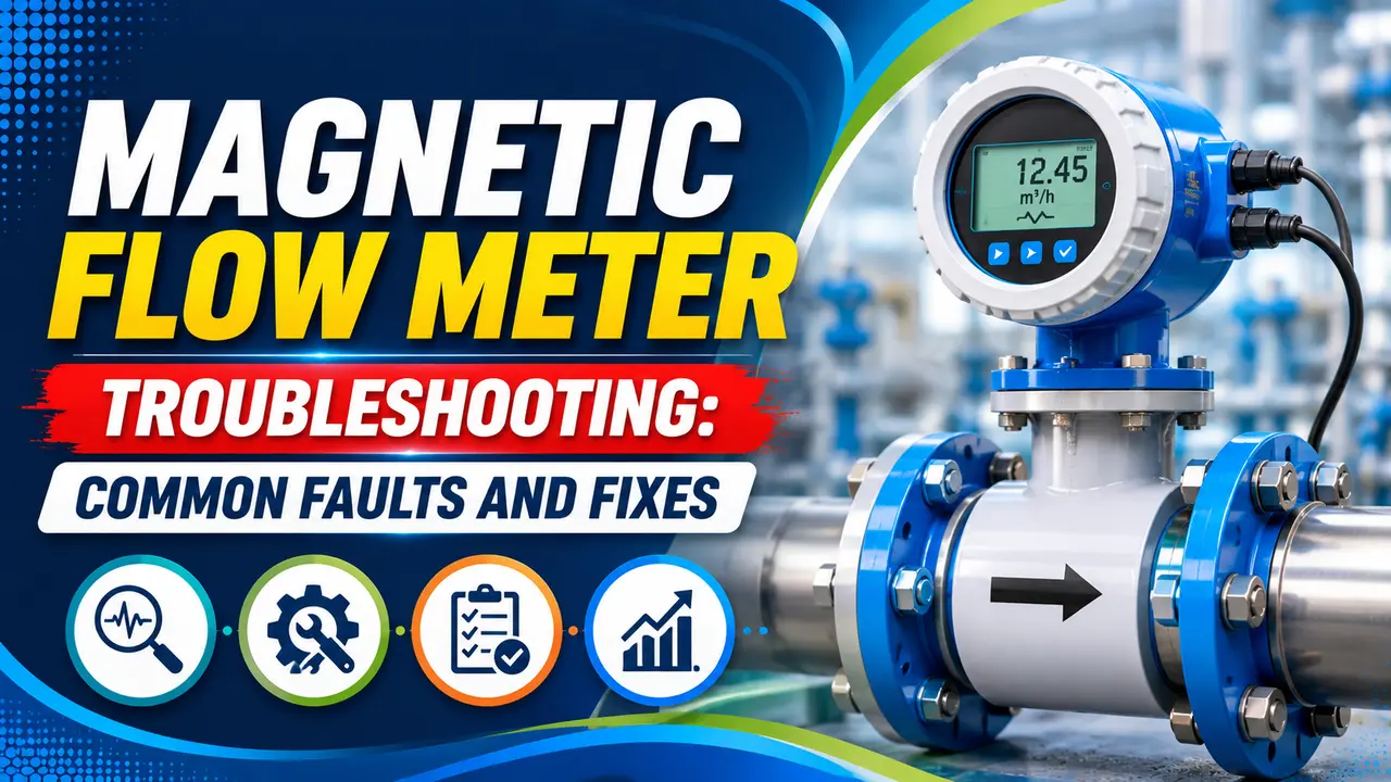
Magnetic Flow Meter Troubleshooting: What a Mag Flow Meter Requires
A magnetic flow meter works only when specific installation conditions are met. Confirming these conditions first eliminates the most common fault causes before opening any junction box.
- Fluid must be conductive -- minimum 5 µS/cm for most meters, 20 µS/cm recommended. Pure water, hydrocarbons, and gases will not work.
- Pipe must be full -- a partially filled pipe means the measured EMF does not represent the average velocity across the full bore. The meter reads low or erratically.
- Correct installation orientation -- horizontal installation requires electrodes at the 3 and 9 o'clock positions (not 12 and 6, which allows gas bubbles to contact the electrodes). See the mag flow sizing and installation guide.
- Minimum straight pipe runs -- typically 5D upstream and 2D downstream of any valve, bend, or fitting.
- Good process earth (grounding) -- the meter electronics measure a millivolt level signal. Poor grounding allows stray currents to corrupt the measurement. This is the single most common cause of erratic readings.
8 Common Faults: Symptoms, Causes and Fixes
What It Looks Like
- 4 to 20 mA output fluctuates when flow is confirmed stopped
- Totaliser accumulates at zero flow
- Small positive or negative reading when valve is closed
Root Causes
- Poor grounding -- stray currents injecting into the signal loop
- Electrode coating -- deposits on electrodes change the electrode impedance balance
- Air bubbles passing the electrodes at low flow
- Zero point not set correctly at commissioning
Corrective Actions
- Verify grounding per manufacturer procedure -- check earth ring continuity
- Perform a zero calibration with the pipe full and flow stopped
- Enable the low flow cutoff (typically 0.5% of range) to suppress creep
- Inspect electrodes for deposits if grounding checks out
What It Looks Like
- 4 mA output with confirmed flow in the pipe
- Empty pipe alarm active even with flow present
- Display shows zero or empty pipe fault code
Root Causes
- Pipe genuinely empty or partially filled
- Fluid conductivity below meter minimum
- Both electrodes coated with insulating deposits
- Electrode lead shorting to earth inside the connection housing
- Coil excitation failure in the transmitter
Corrective Actions
- Confirm pipe is full -- check pressure and vent the high point
- Measure fluid conductivity with a portable conductivity meter
- Check electrode impedance (both electrodes should read within 10% of each other)
- Inspect junction box for water ingress or pinched wires
- Run manufacturer diagnostics -- check coil resistance and drive level
What It Looks Like
- Output fluctuates ±5 to 20% with steady flow
- Noise visible on trend as spikes or oscillation
- Totaliser accumulates inconsistently
Root Causes
- Poor grounding or missing earth rings
- High frequency EMI from nearby VFD, motor, or welding
- Partially filled pipe with air/fluid interface at electrodes
- Two phase flow (entrained gas or solids)
- Signal cable not shielded or shield not grounded at one end only
Corrective Actions
- Verify grounding -- install earth rings if not present, check earth continuity
- Re route signal cable away from power cables and VFD output cables
- Confirm pipe is full -- check for vapour pockets at high points
- Increase the transmitter damping time constant to smooth noise
- Check shield grounding -- single point earth at the transmitter end only
What It Looks Like
- Meter reads 10 to 30% above or below a reference meter
- Error is proportional to flow -- larger at high flow, smaller at low flow
- Zero reading is correct when flow stops
Root Causes
- Incorrect pipe bore entered in the transmitter setup
- Flow profile distortion from insufficient straight pipe
- Liner partially collapsed inward reducing effective bore
- Magnetic field strength reduced from coil degradation
- Calibration factor (K-factor) set incorrectly
Corrective Actions
- Verify pipe bore setting in transmitter matches actual flowtube bore
- Check upstream and downstream pipe runs against installation requirements
- Inspect liner visually -- look for bulging, collapse, or chemical attack
- Run coil diagnostics from the transmitter menu
- Verify K-factor against calibration certificate. See K-factor calculation guide.
What It Looks Like
- Empty pipe fault code or alarm on the display
- Output may be 4 mA, 22 mA, or last value depending on failsafe configuration
- Fluid confirmed present by pressure gauges or sample point
Root Causes
- Fluid conductivity too low -- below the detection threshold of the EPD (empty pipe detection) circuit
- Insulating deposits covering the EPD electrode
- EPD sensitivity threshold set too high in transmitter configuration
- Entrapped gas bubble over the electrodes during startup
Corrective Actions
- Measure actual fluid conductivity -- if below 20 µS/cm, EPD may not function reliably
- Clean electrodes and check for coating
- Reduce EPD threshold sensitivity in transmitter configuration
- Vent the high point to remove trapped gas and re-prime the line
What It Looks Like
- Totaliser counts down instead of up
- 4 to 20 mA reads near 4 mA even with confirmed forward flow
- Meter may show negative flow value on display
Root Causes
- Flowtube installed backwards -- flow arrow on body pointing against process flow direction
- Flow direction parameter set incorrectly in transmitter
- Genuine reverse flow in the process (check pump and valve logic)
Corrective Actions
- Check flow arrow on flowtube against actual process flow direction
- If flowtube orientation is correct, change the flow direction parameter in the transmitter configuration
- Investigate process for reverse flow conditions before reversing the meter setting
What It Looks Like
- Transmitter displays electrode coating alarm or high impedance fault
- Reading may be stable but diagnostic flag is active
- Reading drifts progressively over weeks or months
Root Causes
- Scale or biofilm deposit on the electrode surfaces
- Chemical attack on electrode material (wrong electrode material for the fluid)
- Grease or oil coating from process fluid
- Polymerisation of process fluid on electrode surface
Corrective Actions
- Inspect and clean electrodes -- mild acid clean for scale, mechanical clean for biofilm
- Check electrode material compatibility with process fluid and temperature
- If coating recurs rapidly, consider an abrasion resistant electrode material (platinum, tantalum) or a self-cleaning electrode design
- Review CIP (Clean In Place) frequency for food and beverage applications
What It Looks Like
- DCS input reads 0 mA, 3.6 mA, or 21 mA (open or short circuit)
- Local display on transmitter shows a valid reading
- DCS shows bad quality flag on the tag
Root Causes
- Open circuit in the 4 to 20 mA loop cable (broken wire, corroded terminal)
- Loop supply voltage too low -- most transmitters need 12 to 24 V across terminals at 20 mA
- Loop resistance too high -- check total loop resistance including DCS input impedance
- Incorrect transmitter wiring (2-wire vs 4-wire connection error)
- DCS input card fault or channel configuration error
Corrective Actions
- Measure loop current at the transmitter output terminals -- if correct here, fault is downstream
- Check loop supply voltage: minimum 12V DC across transmitter terminals at 20 mA output
- Verify total loop resistance -- should not exceed (Vsupply − 12) / 0.020 ohms
- Inspect all cable junction boxes for water ingress, corroded terminals, or broken conductors
- See signal conditioning guide for loop current measurement procedure
Interactive Diagnostic Tool
Grounding: The Most Critical Installation Requirement
Magnetic flow meters measure a millivolt level signal generated by the fluid moving through the magnetic field. Any stray current in the process fluid or piping that is not properly referenced to the meter's signal earth will appear as a false flow signal.
Earth rings fit between the flowtube flanges and the pipe flanges, contacting the process fluid to provide a reference earth for the meter electronics.
Without them -- or with corroded rings -- stray pipeline currents inject directly into the measurement. The electromagnetic interference guide covers how stray currents originate and how to suppress them.
Commissioning Checklist
| Check | Requirement | How to Verify |
|---|---|---|
| Flowtube orientation | Flow arrow pointing in direction of process flow | Visual check against piping isometric drawing |
| Electrode position | Horizontal pipe: electrodes at 3 and 9 o'clock. Vertical pipe: any orientation. | Visual check of electrode nozzle position |
| Straight pipe | Minimum 5D upstream, 2D downstream of any disturbance | Measure from nearest elbow, valve, or reducer |
| Earth rings | Both flanges, clean metal to fluid contact, continuity confirmed | Milliohm meter: flowtube earth to pipe earth under 1 Ω |
| Signal cable routing | Separate conduit or tray from power cables; shield grounded at transmitter end only | Physical inspection of cable route and junction boxes |
| Fluid conductivity | Above meter minimum -- typically 5 µS/cm, 20 µS/cm recommended | Portable conductivity meter at nearby sample point |
| Pipe full | Pipe fully primed and pressurised before zero calibration | Pressure gauges upstream and downstream both showing positive pressure |
| Zero calibration | Performed with pipe full and zero flow confirmed at a closed valve | Isolate downstream; observe output is stable at 4 mA; trim zero if offset present |
| Transmitter settings | Pipe bore, full scale flow, low flow cutoff, damping, flow direction, failsafe mode | Review configuration report against instrument datasheet |
| Loop check | 4 mA at zero flow, 20 mA at calibrated full scale flow, correct value at DCS | Loop calibrator at transmitter output; verify DCS displays correct engineering unit value |
Watch: Magnetic Flow Meter Troubleshooting Guide
Magnetic Flow Meter Troubleshooting Questions
External References
- Rosemount 8700 Magnetic Flowmeter -- Installation and Troubleshooting Guide -- Emerson
- Magnetic Flowmeter Troubleshooting Guide -- Yokogawa
What We Learn Today
- Grounding is the first check on every mag flow fault -- stray currents corrupt the millivolt level measurement signal
- The pipe must be full for a valid reading -- partial fill causes low readings and empty pipe alarms
- Fluid conductivity must exceed 5 µS/cm (20 µS/cm recommended) -- pure water and hydrocarbons will not work
- Zero calibration must be done with the pipe full of process fluid and flow stopped at a confirmed closed valve
- Erratic output points to grounding or EMI; span error points to bore setting, K-factor, or installation geometry
- Electrode coating is diagnosed by high impedance alarms and resolved by cleaning -- the deposit type determines the cleaning method