
In a pure resistor, voltage and current rise and fall together, perfectly in step.
Add an inductor or capacitor to that circuit and the two waveforms drift apart in time, and that drift, measured in degrees, is the phase angle that governs everything from power factor to motor performance.
Phase angle in an AC circuit is the difference, measured in degrees, between the voltage and current waveforms, caused by reactive elements like inductors and capacitors, and it is calculated as θ = tan⁻¹(X ÷ R), where X is reactance and R is resistance.
What is Phase Angle in AC Circuits?
A purely resistive AC circuit is the simplest case: voltage and current peak at exactly the same instant, cross zero at exactly the same instant, and stay perfectly synchronized for as long as the circuit runs.
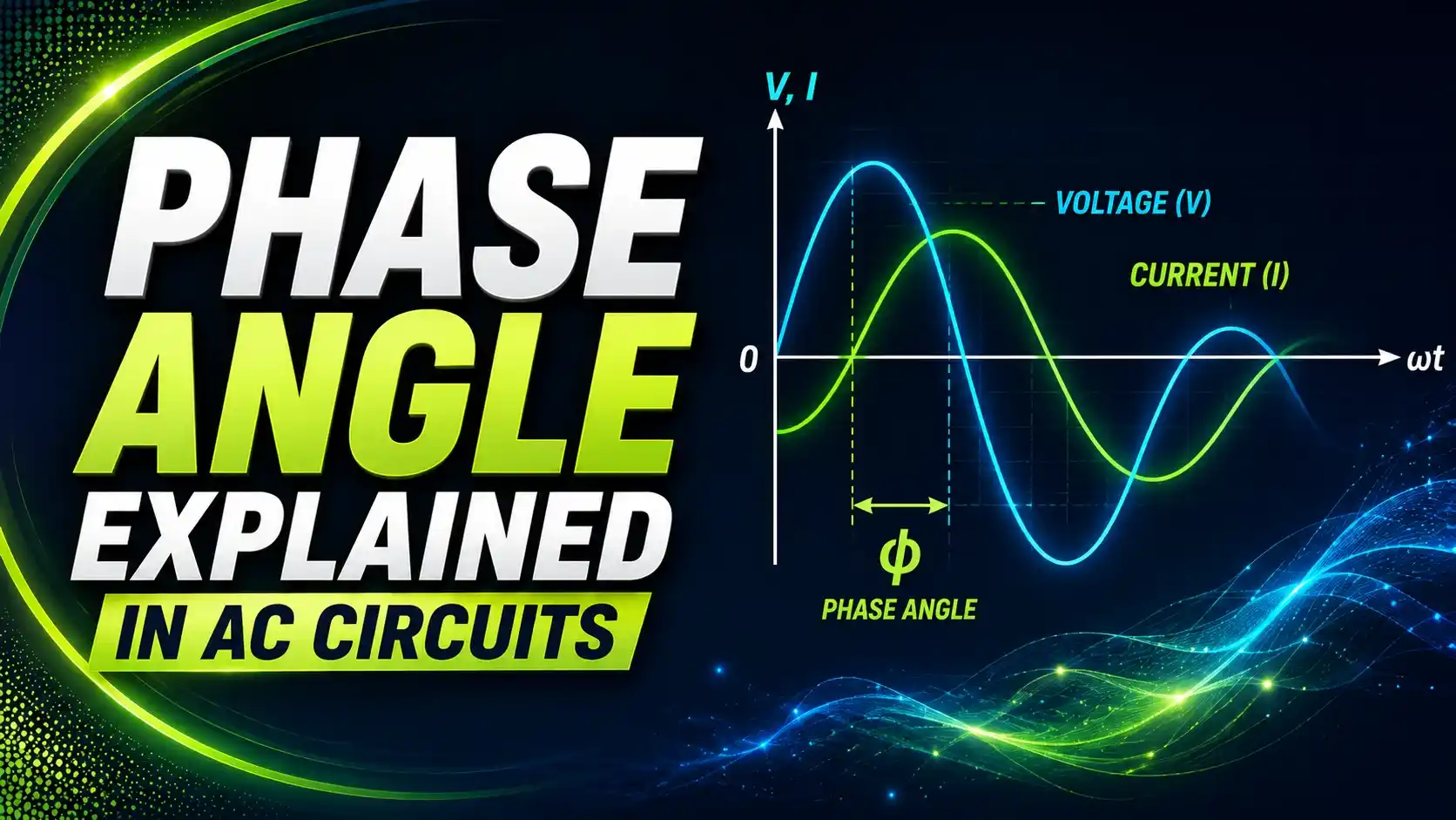
Real circuits rarely stay that simple. Motors, transformers, and fluorescent ballasts are inductive. Power factor correction banks and some electronic loads are capacitive. Both push the current waveform out of step with the voltage waveform, and the size of that shift, the phase angle, determines how efficiently the circuit actually delivers usable power.
Per All About Circuits' explanation of AC inductor behavior, an ideal inductor pushes current a full 90 degrees behind voltage, while an ideal capacitor pushes it 90 degrees ahead, and every real circuit sits somewhere between these two extremes depending on its mix of resistance and reactance.
This guide breaks down what phase angle physically represents, the formula that calculates it from resistance and reactance, and why it's the same number engineers already know as the arccosine of power factor.
Visualizing Phase Angle on a Waveform
The horizontal distance between where the two waves cross zero, expressed as an angle rather than a time delay, is the phase angle. In an inductive circuit like the one shown, current lags behind voltage. In a capacitive circuit, the current wave would instead lead, crossing zero before voltage does.
The Impedance Triangle
Resistance, reactance, and impedance form a right triangle, and the phase angle is the angle between the resistance leg and the impedance hypotenuse. This is exactly the same triangle used in power factor calculations, just labeled in ohms instead of watts and VARs.
θ = tan⁻¹(X ÷ R), where X is the net reactance (inductive minus capacitive) and R is the circuit's resistance. A purely resistive circuit has X = 0, so θ = 0°. A purely reactive circuit has R approaching 0, pushing θ toward 90°.
Try It: Phase Angle Calculator
Enter a circuit's resistance and net reactance to calculate the phase angle and see whether the circuit is leading, lagging, or purely resistive.
A Real Worked Example
An induction motor circuit has 30Ω of resistance and 40Ω of inductive reactance at its operating frequency.
Impedance Z = √(30² + 40²) = √(900 + 1600) = √2500 = 50Ω. Phase angle θ = tan⁻¹(40 ÷ 30) = tan⁻¹(1.333) = 53.1°.
That 53.1° phase angle corresponds to a power factor of cos(53.1°) = 0.6, meaning current lags voltage enough that the circuit needs power factor correction to run efficiently, exactly the kind of motor load a phase angle calculation is used to diagnose before specifying capacitor banks.
Leading vs Lagging: What the Words Actually Mean
Lagging Power Factor
Current crosses zero after voltage does. Caused by inductive loads like motors, transformers, and ballasts. The most common condition in industrial facilities, and the reason most power factor correction adds capacitance.
Leading Power Factor
Current crosses zero before voltage does. Caused by capacitive loads or over-correction from an oversized capacitor bank. Some utilities penalize a leading power factor just as heavily as a lagging one.
Per Wikipedia's explanation of leading and lagging current, the terms describe current relative to voltage specifically, not the reverse, which is a common source of confusion when the convention gets flipped in casual conversation.
Phase Angle by Circuit Type
Real R-L or R-C circuits fall somewhere between 0° and 90°, with the exact value set by the ratio of reactance to resistance at the operating frequency. Since reactance itself depends on frequency, the same physical circuit can have a different phase angle at 50 Hz than it does at 60 Hz, or in the presence of harmonic frequencies.
Phase Angle and Power Factor Are the Same Number
Power factor is simply the cosine of the phase angle. Every capacitor bank sizing calculation that starts from a target power factor is, underneath the arithmetic, targeting a specific phase angle between voltage and current.
Do's and Don'ts of Working With Phase Angle
✓ Do
- Calculate net reactance (inductive minus capacitive) before finding the phase angle on a mixed circuit
- Remember that power factor equals cos(θ), so the two describe the same physical relationship
- Account for frequency when calculating reactance, since XL and XC both depend on it
- Use phase angle sign or lead/lag terminology consistently, always relative to voltage
✗ Don't
- Assume a purely resistive phase angle of 0° for circuits with any inductive or capacitive component
- Confuse leading and lagging, the reference is always current relative to voltage, not the other way around
- Ignore harmonics, which introduce phase relationships at frequencies beyond the fundamental
- Treat impedance as a simple sum of resistance and reactance instead of a right-triangle relationship
Reference Materials on Phase Angle
FAQs on Phase Angle in AC Circuits
External References
- AC Inductor Circuits: Reactance and Impedance, All About Circuits
- Leading and Lagging Current, Wikipedia
What we learn today
- Phase angle is the time-based shift, measured in degrees, between voltage and current waveforms caused by circuit reactance.
- It's calculated as θ = tan⁻¹(X ÷ R), using the same right-triangle relationship as the resistance-reactance-impedance triangle.
- A worked example shows a 30Ω resistance and 40Ω inductive reactance motor circuit producing a 53.1° lagging phase angle and 0.6 power factor.
- Lagging phase angle (inductive) is far more common industrially than leading phase angle (capacitive), which is why most power factor correction adds capacitance.
- Power factor equals cos(θ), meaning every power factor value corresponds directly to a specific phase angle.