
A displacer never floats. It hangs fully submerged and gets lighter as the liquid rises, and that one detail is the key to understanding every displacer level transmitter ever built.
The displacer level transmitter working principle relies on Archimedes' law: a body immersed in liquid loses apparent weight equal to the weight of the liquid it displaces, and that weight loss is what the transmitter actually measures.
Ask an engineer to name a level instrument that still works reliably after decades in a high pressure hydrocarbon vessel, and displacer transmitters usually come up first. They're mechanically simple, they tolerate extreme temperature and pressure, and unlike many differential pressure instruments, they measure something a level transmitter genuinely cares about, actual buoyant force, not an indirect signal that has to be converted.
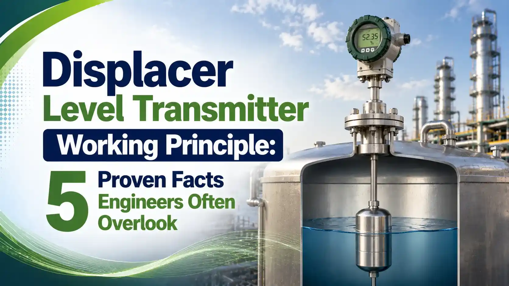
The idea traces back more than two thousand years to Archimedes' principle: a body submerged in a fluid experiences an upward buoyant force equal to the weight of the fluid it displaces. A displacer level transmitter turns that ancient physics into a modern 4 to 20 mA signal, using either a torque tube or a spring and LVDT to sense the tiny change in apparent weight as level rises and falls.
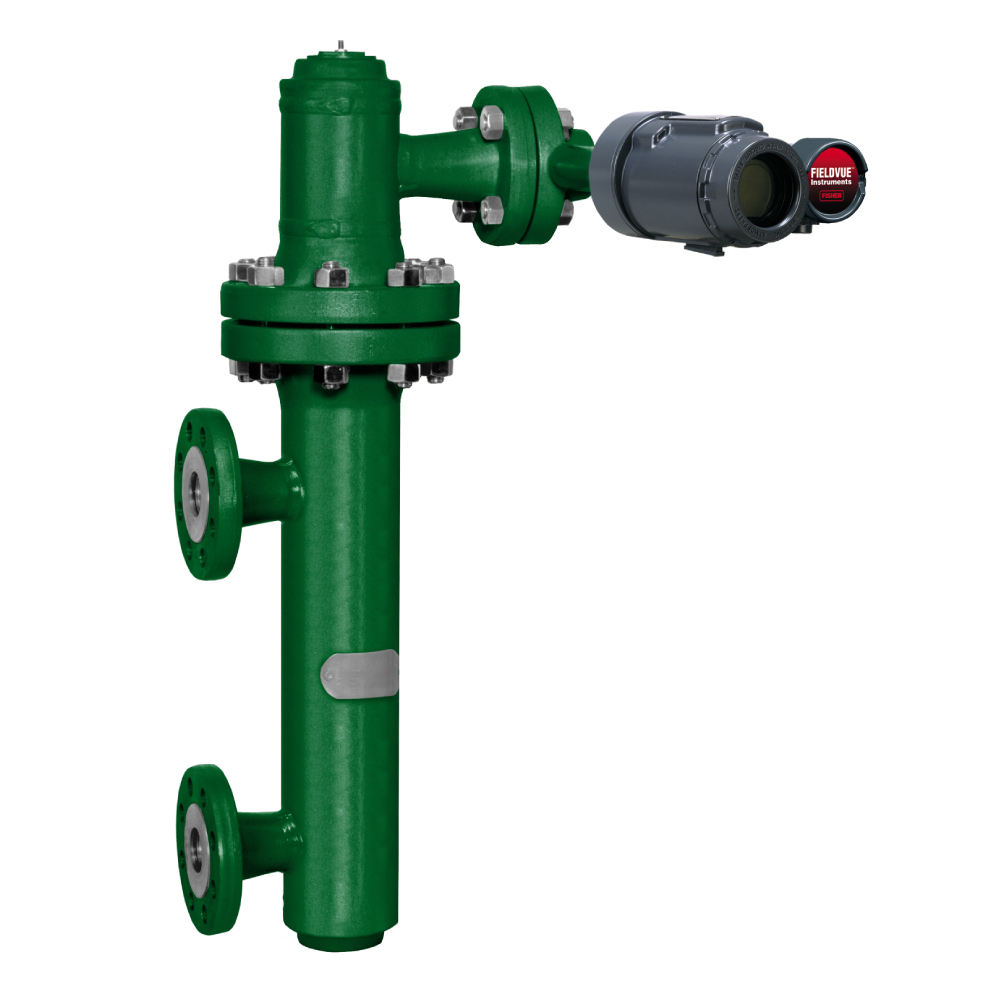
The 5-Step Displacer Level Transmitter Working Principle
Every displacer transmitter, whatever brand or design, goes through the same five steps to turn a rising liquid level into a usable signal.
Displacer Hangs in the Vessel
A dense cylindrical displacer, always heavier than the process fluid, hangs from a torque tube or spring inside a cage or directly in the vessel.
Level Rises, Submersion Increases
As liquid level climbs, a greater portion of the displacer's length becomes submerged in the fluid.
Buoyant Force Increases
Archimedes' principle takes over: buoyant force grows in direct proportion to the submerged volume.
Apparent Weight Drops
The displacer appears lighter to whatever is holding it, and that weight loss is exactly what the sensor is built to detect.
Signal Output
A torque tube twist or LVDT core movement is converted electronically into a 4 to 20 mA signal proportional to level.
Torque Tube vs Spring/LVDT Displacer Designs
Nearly every displacer level transmitter working principle in the field today uses one of two mechanisms to get the buoyancy signal safely out of a pressurized vessel.
Torque Tube Design
The displacer's weight change twists a sealed metal tube. The tube acts as both a torsional spring and a frictionless, leak proof pressure seal between the process and the electronics.
Range Spring / LVDT Design
The displacer hangs from a range spring, and its vertical motion moves an LVDT core, generating a voltage without relying on a twisting tube at all.
Whichever mechanism is used, every displacer installation shares the same core components, and knowing them makes any manufacturer's manual easier to read.
A displacer is not a float. A float rides on the surface and moves nearly the full distance the liquid moves. A displacer stays almost stationary and submerged, and the transmitter reads a force change instead of a position change.
Buoyant Force and Apparent Weight Formula
The buoyant force on a displacer follows directly from Archimedes' principle, and apparent weight is simply the displacer's weight in air minus that buoyant force.
Wa = W - Fb
A = displacer cross sectional area (m2), h = submerged length (m)
W = displacer weight in air (N), Wa = apparent weight (N)
Example: displacer diameter = 38 mm, submerged length = 0.3 m, liquid density = 850 kg/m3
A = π x (0.019)^2 = 0.001134 m2
Fb = 850 x 9.81 x 0.001134 x 0.3 = 2.84 N
If W = 25 N in air, Wa = 25 - 2.84 = 22.16 N
Interface Level Measurement Formula
Displacers are also widely used to measure the interface between two liquids of different density, such as oil sitting on top of water in a separator. The math simply adds a second density term.
ρ2 = lower liquid density, S = displacer cross section, H = displacer length, h_i = interface height
This equation only holds when the displacer spans both liquids and just one variable, either total level or interface height, is changing at a time.
Displacer vs Float Level Measurement
Both technologies use buoyancy, but they measure completely different things and behave very differently in service.
| Property | Float | Displacer |
|---|---|---|
| What moves | Rides on the surface, full travel with level | Stays nearly stationary, submerged throughout range |
| What's sensed | Position of the float | Change in buoyant force (apparent weight) |
| Density sensitivity | Low | High, ideal for interface and specific gravity work |
| Typical pressure/temperature rating | Moderate | High, common in refinery and hydrocarbon service |
| Best suited for | Simple tank level, on/off switching | Level, interface, and density in demanding process vessels |
Where Displacer Level Transmitters Are Used
Oil and Gas Separators
Oil water interface measurement in three phase separators.
Boiler Drums
High pressure, high temperature steam drum level control.
Distillation Columns
Reboiler and reflux drum level in refinery towers.
Chemical Reactors
Corrosive and viscous liquid level tracking.
Density Monitoring
Specific gravity tracking where composition drifts slowly.
Custody Transfer
Accurate interface level for product handoff measurement.
Advantages and Limitations of Displacer Level Transmitters
✓ Advantages
- Handles extreme pressure and temperature better than most level technologies
- Directly measures interface level and specific gravity, not just total level
- Few moving parts, with a torque tube design offering a frictionless process seal
- Long service history with well understood failure modes
✗ Limitations
- Accuracy depends entirely on the process fluid density staying stable
- Vulnerable to coating, corrosion, or buildup changing the displacer's mass
- Torque tubes can fatigue or crack after years of repeated twisting
- Recalibration for a new fluid density requires real engineering calculation
Calibrating a Displacer Level Transmitter
Displacer transmitters are factory calibrated for a specific process fluid density, but most calibration checks in the field are done with plain water since it's simple and always available. That mismatch has to be corrected mathematically before the check means anything.
If a transmitter is set for a hydrocarbon with a specific gravity of 0.85 and the technician instead fills the chamber with water at specific gravity 1.0, the buoyant force at 100% level will be higher with water than the transmitter expects. The equivalent water level that produces the same buoyant force as a full column of the process fluid has to be calculated first, and only that adjusted level should be used to set the 4 mA and 20 mA points.
Two calibration methods are common in the field. A wet calibration floods the cage with a known fluid at known levels and checks the output at each point. A dry calibration instead suspends the displacer from a precision scale and pulls it upward with a calculated force to simulate buoyancy at each calibration point, without needing to fill or drain the vessel at all.
Live Displacer Buoyancy Calculator
Enter the displacer diameter, submerged length, liquid density, and weight in air to calculate buoyant force and apparent weight.
Reference Materials on Displacer Level Transmitters
FAQs on Displacer Level Transmitter Working Principle
External References
- Displacement and Displacer Level Instrumentation, Control.com Textbook
- Fisher 249 Series Caged Sensors, Emerson
- Alternative for Displacer with Torque Tube, Mercon
- Fisher 249 Caged Displacer Sensors Instruction Manual, Emerson
- Displacer Level Technologies Comparison, Delta Mobrey
What we learn today
- The displacer level transmitter working principle rests on Archimedes' law: apparent weight loss is directly proportional to the submerged volume of the displacer.
- A displacer is always denser than the process fluid and stays nearly stationary, unlike a float which rides on the surface.
- Torque tube and range spring/LVDT are the two main mechanisms for transferring the buoyancy signal out of a sealed vessel.
- The same buoyancy math extends directly to interface level measurement between two liquids of different density.
- Accuracy depends entirely on stable process fluid density, making recalibration essential whenever the fluid composition changes.