
Instead of a voltage source and a series resistor, the theorem reduces any linear circuit down to a single current source and a parallel resistor. Here is exactly how that equivalent is found, with a real circuit diagram and a live calculator you can try right now.
What Is Nortons Theorem?
Norton's Theorem states that any linear circuit containing several energy sources and resistances can be replaced by a single constant current source in parallel with a single resistor, as seen from two output terminals.
Proposed by Bell Labs engineer Edward Norton in 1926, this theorem is often called the dual of Thevenin's Theorem, since it delivers the exact same simplification using a current source instead of a voltage source.
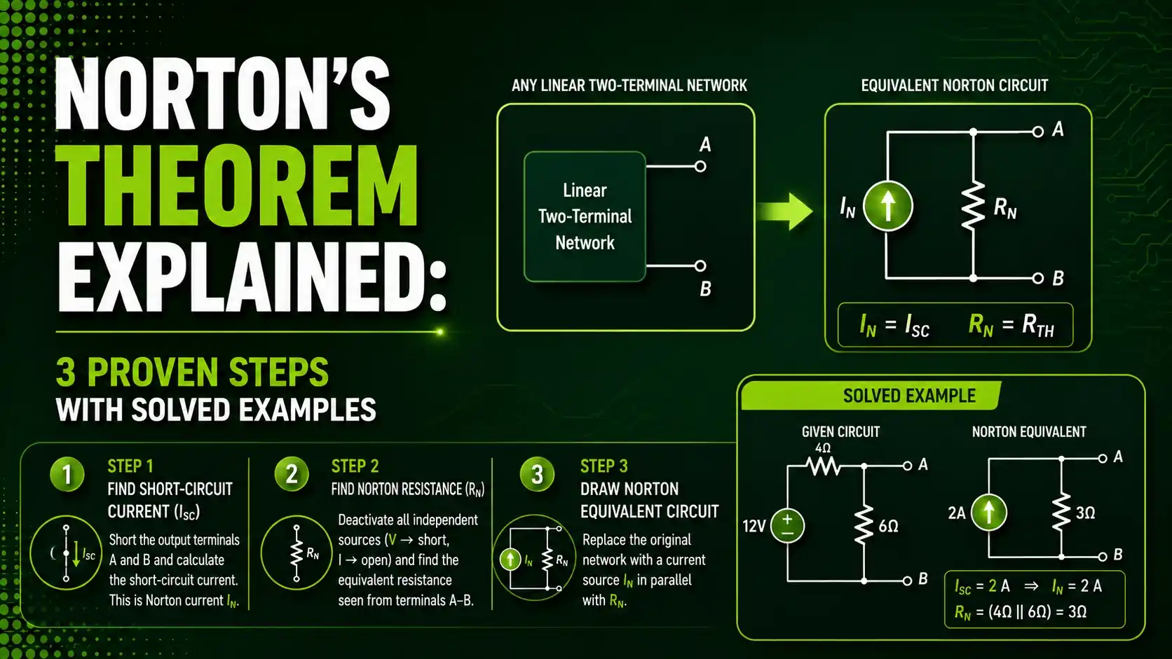
The theorem builds on the same foundation as Kirchhoff's Current Law and Kirchhoff's Voltage Law, and can be converted directly to and from a Thevenin equivalent.
This guide covers the three proven steps behind the theorem, with a real solved example you can follow from start to finish.

How Norton's Theorem Simplifies a Circuit
Every application of this method follows the same four-stage process, closely mirroring Thevenin's approach but with one key difference.
Remove the Load
Disconnect the specific resistor or component whose voltage or current you want to find.
Short the Terminals to Find IN
Place a short circuit across the open terminals and calculate the resulting current, this becomes the Norton current.
Find the Equivalent Resistance
Deactivate all sources, then calculate the resistance looking back into the network, exactly as with Thevenin resistance.
Reconnect and Analyze
Rebuild the circuit as a current source in parallel with a resistor, then reconnect the load to solve easily.
3 Proven Steps to Master Norton's Theorem
These three ideas explain why the method works and what genuinely separates it from Thevenin's approach.
Shorting the Terminals Replaces Removing the Load
Where Thevenin's Theorem opens the terminals to find a voltage, Norton's Theorem shorts them together to find a current. That single difference in step 2 is what separates the two methods.
Norton Resistance Equals Thevenin Resistance
Finding RN uses the exact same procedure as finding Rth: deactivate every independent source and measure the resistance looking back into the network from the open terminals.
Norton and Thevenin Equivalents Convert Instantly
Since both equivalents describe the exact same circuit behavior, IN always equals Vth divided by Rth, letting you convert between the two forms without redoing the analysis.
A Real Solved Example
Using the same familiar circuit as our Thevenin's Theorem guide, a 20V source, a 10-ohm resistor, and a 20-ohm resistor, feeding a 40-ohm load resistor.
What is happening: Shorting the output terminals together makes the 10-ohm and 20-ohm resistors sit in parallel, each carrying its own current directly from the source, and those two currents add up to the total Norton current.
A real example: With the terminals shorted, the 10-ohm branch carries 20V/10Ω = 2A, contributing the entire Norton current in this particular circuit arrangement.
Why it works: Once IN and RN are known, reconnecting the 40-ohm load to this simple current-source-and-resistor equivalent produces the exact same current and voltage the original circuit would deliver.
This matters most when comparing load options quickly. Once IN and RN are calculated a single time, swapping in a new load resistor value takes nothing more than a simple current divider calculation, rather than a full re-analysis of the original network.
Consider a design team testing five candidate loads against the same current-limited sensor output. Rebuilding the full original network from scratch for each candidate would waste real engineering time on the exact same source and internal resistance every single pass. Reducing that source network to its Norton equivalent just once turns each of the five evaluations into a quick current-divider calculation instead.
Formula for Load Current Using Norton Values
Once IN and RN are known, finding the load current is a straightforward current divider calculation.
Load current: IL = IN × RN / (RN + RL)
Norton-Thevenin conversion: IN = Vth / Rth, and RN = Rth
Worked example: IN = 2A, RN = 6.67Ω, RL = 40Ω
IL = 2 × 6.67 / (6.67 + 40) = 0.286A
Try It: Norton Equivalent Calculator
Enter a source voltage and two resistor values to find IN and RN, then see the resulting load current.
Norton's Theorem vs Thevenin's Theorem
| Feature | Norton's Theorem | Thevenin's Theorem |
|---|---|---|
| Equivalent Source Type | Current source | Voltage source |
| Source Arrangement | Parallel with resistance | Series with resistance |
| Key Step 2 Action | Short the output terminals | Open the output terminals |
| Resistance Calculation | Identical to Rth | Identical to RN |
| Best For | Circuits more natural in current form | Circuits more natural in voltage form |
Applications of the Theorem
Current Divider Analysis
Norton's equivalent turns load variation studies into simple current divider math.
Current Source Modeling
Real current-output sensors and circuits are naturally modeled using Norton form.
Maximum Power Transfer Analysis
Maximum power to a load occurs when RL equals RN, same condition as with Rth.
Transistor Output Modeling
Certain transistor output stages are more naturally represented as current sources.
Circuit Simulation Preprocessing
Simulators sometimes prefer a Norton equivalent for numerical stability in certain solvers.
Load Variation Studies
Engineers swap different load values against one fixed Norton equivalent quickly.
Notice how closely this list mirrors the applications listed for Thevenin's equivalent. That overlap is expected, since both methods describe the exact same underlying circuit, just expressed through a different pair of numbers. The deciding factor for which one to reach for is almost always which form, current-based or voltage-based, fits more naturally with the rest of the surrounding circuit.
Advantages and Limitations of the Theorem
Why Norton's Theorem Is So Useful
Limitations to Keep in Mind
Download Norton References
These two academic references go deeper into Norton and Thevenin equivalent circuits.
6.200 Notes: Thevenin-Helmholtz and Mayer-Norton Theorems
Official MIT lecture notes deriving both Norton and Thevenin equivalents
ECE 10A Lecture 16: Thevenin and Norton Equivalent Circuits
UC Santa Barbara lecture notes with additional worked examples
Reading both side by side is worthwhile, since seeing the same derivation presented by two different instructors often clarifies exactly which step was previously unclear.
Watch: Norton's Theorem Explained
This video walks through applying the theorem to solve a real circuit.
FAQs on Norton's Theorem
External References
- MIT 6.200, Thevenin-Helmholtz and Mayer-Norton Theorems
- UC Santa Barbara, ECE 10A Lecture 16, Thevenin and Norton Equivalent Circuits
- Electronics Tutorials, Norton's Theorem Tutorial for DC Circuits
- YouTube, Norton's Theorem Explained, DC Circuit Analysis
What we learn today
- Norton's Theorem reduces any linear network to a single current source in parallel with a single resistance, as seen from two terminals.
- The key procedural difference from Thevenin's Theorem is shorting the terminals to find IN, rather than opening them to find Vth.
- RN and Rth are always numerically identical for the same circuit, since both measure the same resistance with sources deactivated.
- Norton and Thevenin equivalents convert directly into one another using IN = Vth / Rth.
- The theorem is especially valuable for testing multiple load values quickly against the same source network.