
The same three resistors can behave in completely different ways depending purely on how they are wired together. Here is exactly how these two circuit types differ, with real circuit diagrams and a live calculator you can try right now.
What Are Series and Parallel Circuits?
In a series circuit, components are connected end-to-end along a single path, so the same current flows through every one of them. In a parallel circuit, components connect across the same two points, so each one sees the same voltage.
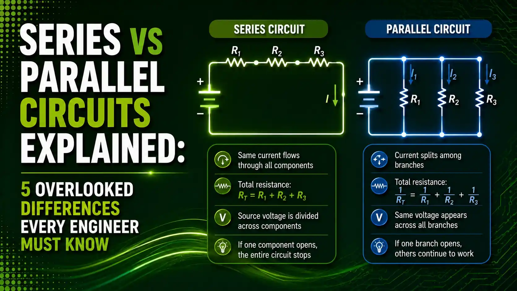
That one structural choice, single path versus multiple paths, cascades into completely different behavior for current, voltage, resistance, and even how a circuit fails. Understanding both is essential background for the Kirchhoff's Current Law and Kirchhoff's Voltage Law guides covered previously, since both laws describe exactly these two connection types.
This guide covers the five most overlooked differences between the two circuit types, from resistance behavior to what happens when a single component fails.
Series vs Parallel Circuits: Core Definitions
Before comparing the details, it helps to see each definition side by side.
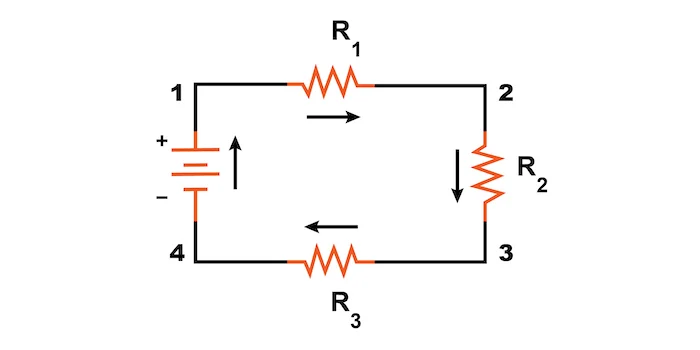
Series Circuit
All components connect end-to-end, forming a single path for current. Every component shares exactly the same current, and voltage divides across them.
Best for: applications needing a fixed, shared current.
Parallel Circuit
All components connect across the same two nodes, forming multiple paths for current. Every component shares exactly the same voltage, and current divides across them.
Best for: applications needing a fixed, shared voltage.
It is worth stressing that this classification depends entirely on electrical connection, not on how a schematic happens to be drawn on paper. Two resistors can look like they sit side by side visually and still be wired in series, and two resistors drawn one above the other can still be genuinely parallel. The only test that matters is whether current has just one path available, or more than one.
5 Overlooked Differences Between Series and Parallel Circuits
These five differences explain almost every practical decision that comes up when wiring or troubleshooting a real circuit.
Current Behavior
In series, the same current flows through every component, with no other path available. In parallel, current splits across branches, with more current flowing through lower-resistance paths.
Voltage Behavior
In series, the supply voltage divides across each component according to its resistance. In parallel, every branch sees the exact same full supply voltage.
Total Resistance
Series resistances simply add together, so total resistance always increases as components are added. Parallel resistances combine in a way that always reduces total resistance below the smallest individual resistor.
Failure Behavior
If one component fails open in a series circuit, the entire circuit stops working, since there is no other path for current. If one component fails open in a parallel circuit, the remaining branches keep functioning normally.
Power Distribution
In series, since current is shared, the larger resistor dissipates more power. In parallel, since voltage is shared, the smaller resistor dissipates more power, exactly the opposite relationship.
Parallel Circuit Diagram
Notice how every resistor connects between the same two sets of electrically common points, rather than chaining end-to-end.
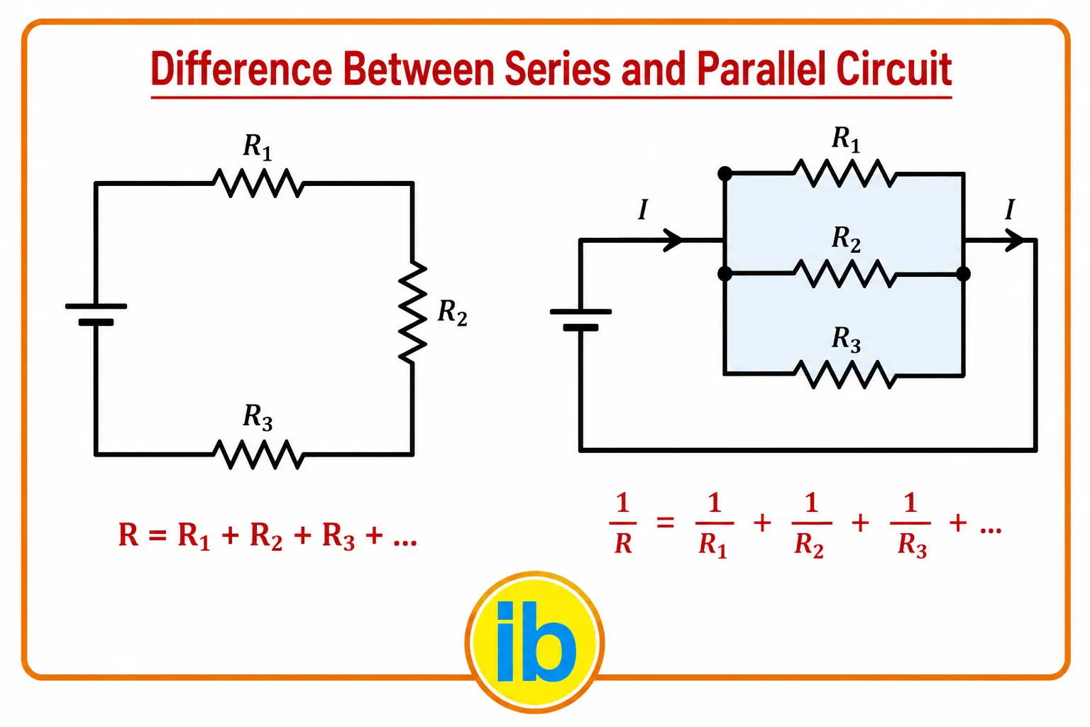
What is happening: Each resistor branch in the parallel diagram connects to the same top node and the same bottom node, so all three resistors are guaranteed to see identical voltage, no matter how different their resistance values are.
A real example: A 10-ohm resistor and a 40-ohm resistor in parallel across a 20V supply each see the full 20V, but the 10-ohm branch carries four times the current of the 40-ohm branch.
Why it works: Since both branches share the same two nodes, Kirchhoff's Voltage Law forces the voltage across each to be identical, while Kirchhoff's Current Law lets the total current split unevenly according to each branch's resistance.
This is why parallel wiring is sometimes called a current divider, mirroring how series wiring is often called a voltage divider. In a current divider, the branch with less resistance always claims a larger share of the total current, following the same inverse relationship that governs how quickly water flows through pipes of different widths. A wider pipe, like a lower resistance, simply lets more flow through for the same driving pressure.
Resistance and Power Behavior Compared
Adding a third, equal-value resistor to a 2-resistor network produces opposite effects depending on wiring.
This reversal is worth sitting with for a moment, since it trips up a surprising number of people learning circuit theory for the first time. Intuitively, adding more components feels like it should always add more resistance to overcome. That intuition holds perfectly for series wiring, but it breaks down completely in parallel, where every new branch simply gives current one more route to flow through, lowering the overall opposition to current flow rather than raising it.
Series and Parallel Resistance Formulas
Both relationships reduce to one core formula each.
Series resistance: Rtotal = R1 + R2 + R3 + ...
Parallel resistance: 1/Rtotal = 1/R1 + 1/R2 + 1/R3 + ...
Worked example: R1 = 10Ω, R2 = 20Ω, R3 = 40Ω
Series: Rtotal = 10 + 20 + 40 = 70Ω
Parallel: 1/Rtotal = 1/10 + 1/20 + 1/40, Rtotal = 5.71Ω
Try It: Series vs Parallel Circuit Calculator
Enter a supply voltage and up to three resistor values, then compare series and parallel wiring side by side.
Series vs Parallel Circuits Comparison Table
| Feature | Series Circuit | Parallel Circuit |
|---|---|---|
| Current | Same through every component | Divides across branches |
| Voltage | Divides across components | Same across every branch |
| Total Resistance | Increases, sum of all resistors | Decreases below smallest resistor |
| Component Failure | Breaks the entire circuit | Only affects that one branch |
| Best For | Fixed shared current applications | Fixed shared voltage applications |
Applications of Series and Parallel Circuits
Battery Packs
Cells in series raise voltage, cells in parallel raise current capacity.
Household Wiring
Outlets and lights wire in parallel so every appliance receives full supply voltage.
Voltage Dividers
Series resistor chains split a supply voltage down to a desired reference level.
String Lighting
Older series-wired light strings go fully dark if a single bulb fails, unlike parallel strings.
Sensor Signal Chains
Series resistor networks set current-limiting and biasing for individual sensor elements.
Power Distribution
Parallel branches let a power supply serve many independent loads reliably.
Real designs rarely commit to one wiring style throughout an entire system. A large LED lighting installation is a good illustration: individual LEDs within a single string are typically wired in series to guarantee each one carries identical current, while multiple such strings are then wired in parallel so that losing one entire string does not darken the whole installation. Recognizing which principle applies at which level of the design is a core skill in practical circuit layout.
Advantages and Limitations of Each Circuit Type
Why Parallel Circuits Dominate Real Wiring
Where Series Circuits Still Make Sense
Download Series and Parallel Circuit References
These two academic references go deeper into series and parallel resistor network analysis.
ECE 205 Lecture 4: Circuit Analysis, Resistors in Series and Parallel
University of Illinois lecture notes on series and parallel resistor networks
OpenStax University Physics: Resistors in Series and Parallel
Open textbook chapter with worked equivalent resistance examples
Watch: Series and Parallel Circuits Explained
This video walks through voltage, current, and resistance behavior in both circuit types.
FAQs on Series vs Parallel Circuits
External References
- University of Illinois, ECE 205 Lecture 4, Circuit Analysis Resistors Series and Parallel
- OpenStax University Physics, Resistors in Series and Parallel
- All About Circuits, What is the Difference Between Series and Parallel Circuits?
- YouTube, Series and Parallel Circuits Explained, Voltage Current Resistance Physics
What we learn today
- Series circuits share one current path, so current stays the same and voltage divides across components.
- Parallel circuits share the same two nodes, so voltage stays the same and current divides across branches.
- Adding resistors in series always increases total resistance, while adding them in parallel always decreases it.
- A single failed component breaks an entire series circuit, but only removes one branch from a parallel circuit.
- Power distribution reverses between the two types: the larger resistor dissipates more in series, the smaller dissipates more in parallel.