
Learn how PLC multiple outputs configuration works in ladder logic, with real rung examples, sequence logic, and an interactive simulator you can try right now.
What Is PLC Multiple Outputs Configuration?
A single PLC rung can drive more than one output coil at the same time. PLC multiple outputs configuration is simply the set of ways you can arrange those coils so the right devices turn on at the right moment.
Suppose you press one start button and you need two pumps to run together. You do not need two separate programs for that. You need one rung, one input, and two output coils placed correctly. That is the whole idea behind PLC multiple outputs configuration.
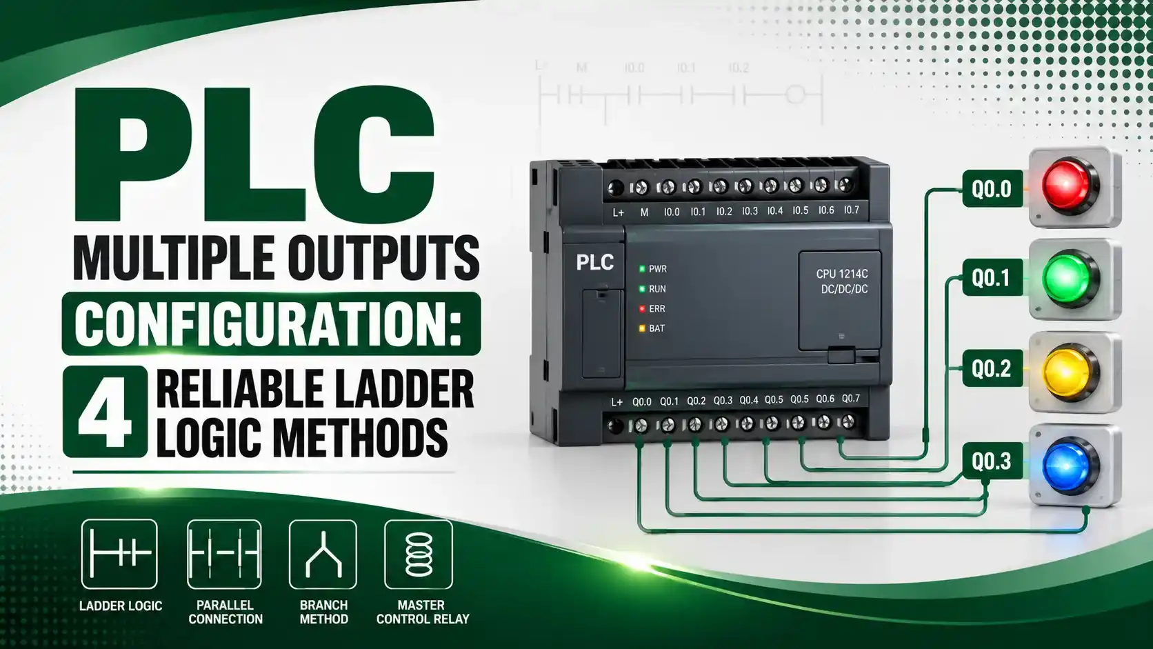
This guide covers four ways to configure multiple outputs in ladder logic: parallel outputs, series interlocked outputs, sequenced outputs, and the marker bit method. You will also see how the same idea looks in ladder logic across different PLC brands, plus a working simulator you can click on this page.
Getting PLC multiple outputs configuration right matters more than it looks. Pick the wrong method and you either waste program space with duplicate rungs, or you accidentally chain two unrelated devices together so a fault on one stops the other. Once you understand the four methods below, you will know exactly which one fits a given job before you even open your programming software.
How a PLC Scans a Rung with Multiple Outputs
Before looking at the four methods, it helps to see what actually happens inside the PLC during one scan. The steps below apply to every method in this article.
Input Contact Closes
The rung starts on the left with one or more contacts. When the required contact or contacts close, power flow reaches the right side of the rung.
PLC Scans Left to Right
Every scan cycle, the PLC checks the rung in order, left to right, top to bottom. It never skips ahead.
All Coils Energize Together
If the rung is true, every output coil on that rung switches on together, whether the coils sit in parallel branches or one after another.
Field Devices Respond
The output module converts each internal bit into a real signal, driving motors, solenoids, lamps, or valves in the field.
4 Ways to Configure Multiple Outputs in PLC Ladder Logic
These four methods cover almost every situation you will meet on the job. Pick the one that matches how your outputs actually depend on each other.
Parallel Outputs
Two or more coils are placed side by side on the same rung, all fed by the same input condition. Every coil turns on and off together, at exactly the same instant.
Best for: starting two pumps together from one start button.
Series Interlocked Outputs
The second output depends on the first output plus an extra permissive contact. One output is simple, the other only runs once a condition is satisfied.
Best for: a pump that should only start after a safety permissive is met.
Sequenced Outputs
Outputs switch on one after another as contacts close in order. Output A needs input A, output B needs A and B, output C needs A, B and C.
Best for: conveyor belts, bag house dampers, and valve sequencing.
Marker Bit Method
One internal marker bit (an internal coil) is set on one rung, then reused as the input condition on several separate output rungs.
Best for: large programs where many outputs share the same trigger logic.
PLC Ladder Rung with Two Outputs Explained
The simplest form of PLC multiple outputs configuration is two coils on one rung, fed by one input. Here is what that rung looks like and why it matters.
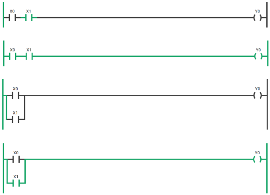
What is happening: One normally open contact sits on the left rail. Two coils, Pump_A and Pump_B, sit in parallel branches on the right. When the contact closes, both coils receive power in the same scan.
A real example: Suppose you need to start two pumps in parallel by pressing a single start button. You wire one input for the start button, then place both pump output coils on the same rung, side by side. Press the button once, both pumps start together.
Why it works: The PLC does not care how many coils are on a rung. It evaluates the left side once, then energizes every coil connected to that same true condition, in the same scan.
One thing to watch: Both output coils still need their own separate output address. You are not sharing one address between two devices, you are simply sharing one input condition between two independent addresses.
PLC Multiple Outputs Configuration: The Logic Behind the Rung
Underneath the graphics, every rung is just a Boolean statement. Writing it out in plain logic makes the four methods much easier to compare.
Output_A = Input_A
Output_B = Input_A AND Input_B
Output_C = Input_A AND Input_B AND Input_C
Worked example: Input_A = 1, Input_B = 1, Input_C = 0
Output_A = 1 (ON)
Output_B = 1 AND 1 = 1 (ON)
Output_C = 1 AND 1 AND 0 = 0 (OFF)
Notice that output C never turns on until all three inputs are true. This one small formula is the entire idea behind sequence logic, which we will look at again further down this article.
Multiple Outputs Configuration Across PLC Brands
The logic stays the same everywhere, but the screen looks a little different depending on which software you use. Click each tab to compare.
Studio 5000 and RSLogix 5000 let you place several output instructions on one rung, either lined up one after another or branched in parallel. Rockwell's own documentation confirms both layouts are valid, though branched parallel coils are generally easier to trace during troubleshooting.
TIA Portal organizes logic into numbered network segments rather than a single continuous ladder. Each network can still hold multiple coils, and Siemens engineers commonly use an internal memory bit (an M-bit) to feed several output networks that need to fire from the same condition.
GX Works shows multiple outputs on a rung using the same branch style as Allen-Bradley, with Y-prefixed output addresses. Mitsubishi documentation for sequence logic commonly shows three or more outputs stepping on in order, matching the sequenced method described in this guide.
In CLICK PLC software, you add a second output coil to the same rung by holding Ctrl and pressing the down arrow while your cursor sits in the output column, which draws a new parallel branch for the additional coil.
PLC Multiple Outputs Configuration Comparison Table
| Method | How It Works | Typical Use Case | Main Advantage | Main Drawback |
|---|---|---|---|---|
| Parallel Outputs | Same input drives two or more coils in branches | Two pumps started together | Simple, both outputs act at once | No independent control of either output |
| Series Interlocked | Second output needs first output plus a permissive contact | Pump that needs a safety permissive | Enforces a required condition | A fault on the first device blocks the second |
| Sequenced Outputs | Each output needs all previous contacts closed too | Conveyor or valve sequencing | Guarantees strict order of operation | Harder to troubleshoot with many steps |
| Marker Bit Method | One internal coil feeds several separate output rungs | Large programs, shared trigger logic | Easy to update logic in one place | Adds one extra internal address to track |
As a quick rule of thumb, start with parallel outputs whenever devices genuinely act independently. Reach for series interlocked outputs only when a real safety or process condition demands it, not just because it looks tidy. Save sequenced outputs and the marker bit method for jobs that truly need strict order or shared triggering across many rungs.
Applications of PLC Multiple Outputs Configuration
Dual Pump Start
One start button energizes two pumps together for parallel liquid transfer.
Conveyor Sequencing
Belts start in order so material never piles up on a downstream section.
Bag House Dampers
Dampers open in sequence so dust collection airflow stays balanced.
Traffic Light Control
Red, yellow, and green outputs step through a fixed timed sequence.
Batch Mixing Valves
Fill valves, mixer motor, and drain valve energize in a strict order.
Elevator Door and Light
A single door-open command also drives the cabin light output.
Advantages and Limitations of Multiple Outputs Configuration
Advantages
Common Mistakes
Try It: PLC Multiple Outputs Configuration Simulator
Toggle the inputs below to see how outputs respond under the two-output method and the sequenced method. This mirrors the exact formulas shown earlier in this article.
PLC Sequence of Outputs: Sequence Logic Explained
Sequence logic is the third method from earlier, and it deserves a closer look since it is the one used most often on real production lines.
What is happening: Until input A closes, none of the other outputs can switch on. Once input A closes, output A turns on. Then, when input B also closes, output B turns on. Finally, when input C also closes, output C turns on.
A real example: Suppose you run a bag house dust collector. Damper A must open first, then the fan motor (output B) can start only once damper A is confirmed open, then the second damper (output C) opens only once the fan is confirmed running.
Why it works: Each output rung simply adds one more contact in series compared to the rung before it. That growing chain of AND conditions is what forces the strict order.
Download PLC Ladder Logic Resources
These two resources go deeper into official multiple-output rung rules and general ladder logic instruction sets.
Logix 5000 Controllers: Ladder Diagram Manual
Official Rockwell Automation guide covering serial and parallel output instructions per rung
The PLC Handbook
Free eBook from AutomationDirect covering ladder logic instructions and program structure
Watch: Sequencing in Ladder Logic
This video walks through building a step-by-step sequence in ladder logic, the same idea behind method 3 in this guide.
FAQs on PLC Multiple Outputs Configuration
External References
- Rockwell Automation, Logix 5000 Controllers Ladder Diagram Manual
- AutomationDirect, The PLC Handbook
- SolisPLC, How to Read Ladder Logic and Ladder Diagrams
- University of Utah, Ladder Logic Fundamentals PLC Tutorial
- YouTube, Sequencing in Ladder Logic: Step by Step
What we learn today
- PLC multiple outputs configuration covers four core methods: parallel, series interlocked, sequenced, and marker bit.
- Every method comes down to one Boolean formula per output, evaluated fresh on every scan.
- Parallel outputs are the safest default when devices do not depend on each other.
- Sequence logic simply adds one more series contact per step to force strict order.
- Never reuse the same output address across two rungs, since only the last executed rung wins.