
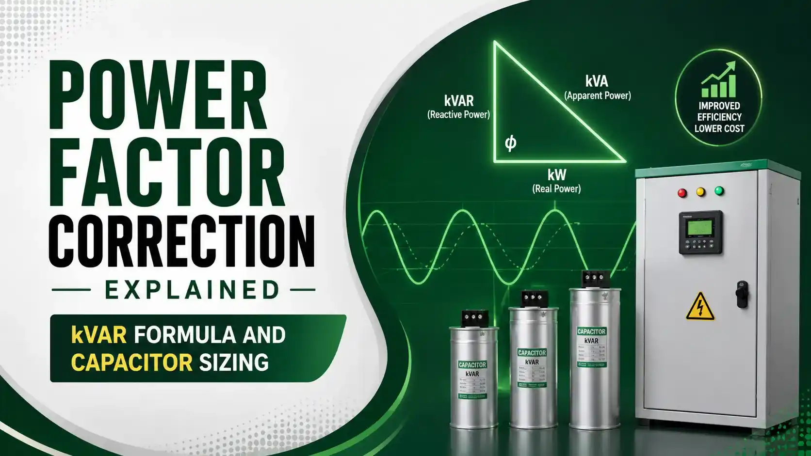
Power Factor Correction Explained: kVAR Formula and Capacitor Sizing
A motor with poor power factor is like a delivery truck hauling mostly empty boxes. The utility still has to send a truck big enough for the full load, even though only part of it is doing useful work.
Power factor correction reduces the reactive power a facility draws from the grid, cutting utility penalties and freeing up electrical capacity. This guide explains the power triangle, the kVAR sizing formula, and gives a live capacitor bank sizing calculator.
What is Power Factor?
Power factor is the ratio between real power (kW), the power that actually does useful work, and apparent power (kVA), the total power the utility must supply to deliver that real power. Inductive loads, such as induction motors, transformers, and fluorescent lighting, draw current that lags voltage, creating reactive power (kVAR) that does no useful work but still has to be supplied and carried by the system.
A low power factor means a facility draws more current than necessary to deliver the same real power, straining cables and transformers and often triggering utility penalty charges once power factor drops below a set threshold, commonly 0.90. Power factor correction fixes this by installing capacitor banks that supply leading reactive power, canceling out the lagging reactive power drawn by inductive loads.
Real Life Example
Think of carrying a mug of beer with a lot of foam on top. The mug looks full, but only the liquid underneath the foam is actually beer you can drink, the foam is just taking up space in the mug without adding any real refreshment.
Reactive power is like that foam: it takes up capacity in the electrical system without doing any real work, and power factor correction is essentially skimming off that foam so more of the mug's capacity carries actual, useful beer.

The Power Triangle
The power triangle: real power (kW) along the base, reactive power (kVAR) vertical, apparent power (kVA) as the hypotenuse. Power factor = cos θ = kW/kVA.
Capacitor Sizing Formula
Capacitor Bank Sizing Calculator
kVAR Capacitor Sizing Calculator
Based on the standard power factor correction formulaApplications
Industrial Motor Loads
Plants with many induction motors are the most common power factor correction candidates.
Fluorescent and HID Lighting
Ballast-driven lighting historically contributes significantly to lagging power factor.
Commercial Buildings
HVAC compressors and building equipment benefit from centralized correction.
Utility Substations
Utilities apply their own correction to manage system-wide reactive power flow.
Individual Large Motors
Dedicated capacitors at large motor terminals correct locally at the source.
Solar and Battery Inverters
Modern inverter-based systems increasingly manage power factor correction electronically.
Power Factor Correction: Video Walkthrough
Frequently Asked Questions About Power Factor Correction
- All About Circuits, Practical Power Factor Correction
- Electrical Engineering Centre, Capacitor Sizing for Power Factor Correction
- Turn2Engineering, Power Factor Correction: Formula, kVAR and Capacitors
What We Learn Today
- Power factor is the ratio of real power to apparent power, and inductive loads cause it to lag
- The power triangle relates real power, reactive power, and apparent power geometrically
- Capacitor banks correct power factor by supplying leading reactive power to cancel lagging reactive power
- Required capacitor size follows Qc = P x (tan θ1 - tan θ2), based on existing and target power factor
- Always size capacitor banks against peak demand, and avoid overcorrection past roughly 0.95 to 0.98