
Level Measurement · Radar Technology · Instrument Selection
Guided Wave Radar vs Non-Contact Radar: 6 Key Differences for Level Measurement Selection
Same underlying physics, same time-of-flight math, completely different engineering trade-offs. This guide compares guided wave radar vs non-contact radar with real dielectric numbers, range limits, a video, and a full do's and don'ts selection guide.
Guided Wave Radar vs Non-Contact Radar: The Core Difference
Both technologies fire a microwave pulse and time how long it takes to come back. That's where the similarity ends. Non-contact radar sends its pulse through open air, straight down from an antenna at the top of the tank, and waits for an echo off the liquid surface. Guided wave radar sends the same kind of pulse down a probe, a rod or cable that actually touches the material. One measures through the air. The other measures along a wire.
That single design choice cascades into everything else. Signal loss, dielectric sensitivity, foam performance, installation limits, fouling risk, even how far each one can reach. Neither technology is simply better. They fail in opposite directions, and picking the right one means knowing which failure mode your tank is more likely to throw at you.
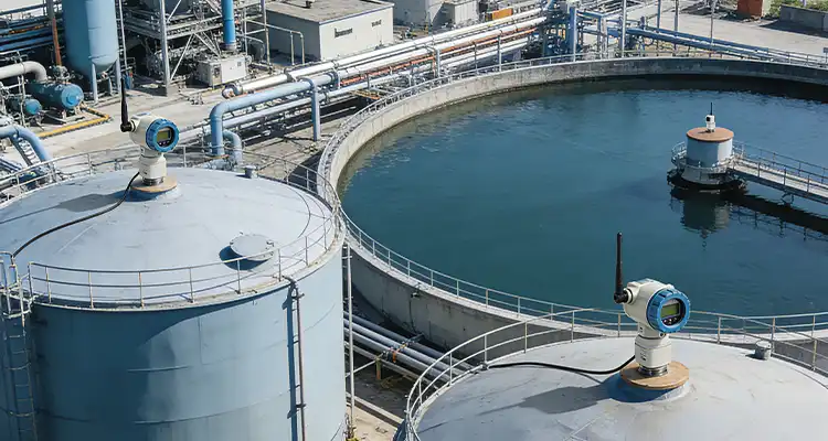
6 Key Differences Between Guided Wave Radar and Non-Contact Radar
Watch: Guided Wave Radar vs Non-Contact Radar Level Measurement Explained
This video walks through both technologies side by side with clear visual comparisons.
Dielectric Constant: The Number That Decides Which Radar Actually Works
Every radar reflection depends on how sharply the dielectric constant changes at the surface being measured. Air sits at 1.0. A bigger jump from that baseline means a stronger, cleaner reflection for either technology.
| Material | Approximate Dielectric Constant |
|---|---|
| Air | 1.0 |
| Light hydrocarbons, gasoline | ~2.0 |
| Glycerin | ~42 |
| Water | ~80 |
Guided wave radar keeps producing a usable, if weaker, reflection well below what non-contact radar can reliably handle, since the probe concentrates the signal energy rather than letting it spread and dilute through open air.
Range, Frequency, and Installation Comparison
| Parameter | Guided Wave Radar | Non-Contact Radar |
|---|---|---|
| Typical maximum range | 30 to 50 m (probe-limited) | Up to 150 m (some high-end units to 120 m on silos) |
| Typical frequency | 1 to 2 GHz | 6, 26, or 80 GHz depending on model |
| Minimum dielectric constant | ~1.4 | ~2 to 3 for reliable operation |
| Contact with process material | Yes, via probe | No |
| Best suited tank size | Small to mid-size, narrow or obstructed vessels | Large, open, unobstructed vessels |
| Interface measurement | Yes, a core strength | Generally not capable |
Do's and Don'ts: Choosing Between Guided Wave Radar and Non-Contact Radar
- Choose guided wave radar for narrow, obstructed, or foam-prone vessels where a stable signal path matters more than reach.
- Choose non-contact radar for large, open, clean tanks where probe length and mechanical wear would become a real problem.
- Check the actual dielectric constant of your process material against both technologies' realistic minimums before committing.
- Use guided wave radar specifically when interface measurement, such as oil on water, is a real requirement.
- Confirm headroom above the tank for probe insertion and removal before specifying guided wave radar.
- Don't install a guided wave probe in a vessel with an aggressive mechanical agitator without checking for probe collision risk first.
- Don't specify non-contact radar for heavy, persistent foam applications without a real performance check on that specific foam type.
- Don't assume a guided wave probe rated for one process automatically transfers to a different tank, the waveguide length is application specific.
- Don't ignore fouling risk on sticky, crystallizing, or polymerizing media when specifying a contact-based probe.
- Don't expect non-contact radar to give a reliable interface reading between two liquids, that's a guided wave radar strength, not theirs.
Quick FAQs: Guided Wave Radar vs Non-Contact Radar
External References
- Kobold: Guide to Radar, Guided Wave Radar and Ultrasonic Level Measurement
- Control Global: Radar Gauge Considerations
- Just Measure It: Guided Wave Radar vs Non-Contact Radar Level Measurement
What we learn today
- Guided wave radar and non-contact radar share the same time-of-flight physics, but a confined probe versus an open-air beam sends their strengths in opposite directions.
- Guided wave radar wins on low dielectric media, foam, vapor, and interface measurement. Non-contact radar wins on range, large clean vessels, and avoiding any probe fouling risk.
- Dielectric constant is best treated as a margin, not a strict pass or fail line, since thin margins tend to fail exactly when conditions get difficult.
- Neither technology is a universal answer. The right choice depends on tank geometry, process material, and which failure mode your application is actually exposed to.