
Industrial Automation · PLC · Power Supply · Redundancy
Redundant Power Supply: 4 Ultimate Rules for Zero Downtime Panels
A single power supply failure can take down an entire control panel in seconds. This guide explains how a redundant power supply actually works, using two SMPS units and a pair of diodes, and gives you a load current calculator to size your own setup correctly.
What Is a Redundant Power Supply?
Most components inside a PLC panel, like the PLC itself, HMI, relays, and instrument power supplies, run on 24V DC. A device called an SMPS, short for switched mode power supply, converts the incoming 110 to 230V AC into that 24V DC. A redundant power supply simply means using two SMPS units together, one acting as primary and the other acting as standby, so a single failure never stops the panel from running.
This idea sits right alongside PLC redundancy switchover as one of the core building blocks of a reliable control system. Without stable 24V power, nothing else in the panel, including redundant controllers, can function at all.
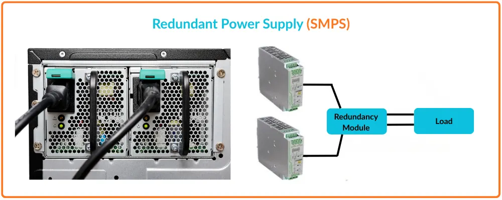
How a Redundant Power Supply Switches Over: 4 Steps
The incoming AC supply is split and fed to both the primary and standby SMPS units at the same time.
→The 24V DC output of each SMPS is fed through its own diode before reaching the common load.
→The two diodes naturally allow only the higher voltage source to pass current through to the load.
→If the primary fails or its voltage drops, the standby's diode instantly takes over without interruption.
The Parts Behind a Redundant Power Supply
Set to a slightly higher output voltage, for example 24V, so it normally carries the full panel load.
Role: the main power source during normal operation.
Set to a slightly lower output voltage, for example 23.5V, so it stays ready without carrying load unnecessarily.
Role: takes over automatically the moment the primary fails.
Two diodes, one at each SMPS output, work together to let only the higher voltage pass to the load.
Role: the core mechanism that makes switchover automatic and uninterrupted.
Many SMPS units include a relay contact that closes when the output goes out of its normal range.
Role: feeds a digital input to the PLC so a failure gets noticed and logged.
Why the Diodes Are the Real Trick
4 Ultimate Rules for a Reliable Redundant Power Supply
SMPS Load Current Sizing Formula
Where:
Sum of All Device Currents = total current drawn by PLC, HMI, relays, and other 24V devices
Safety Margin = extra capacity added for future expansion, typically 20 to 30 percent
Example: PLC 1.5 A, HMI 0.8 A, relays and sensors 2.2 A, margin 25 percent Total = (1.5 + 0.8 + 2.2) × 1.25 = 4.5 × 1.25 = 5.6 A Each SMPS in a redundant pair should be sized to carry the full load on its own, not half of it, since the whole point of redundancy is that either unit can run the panel completely by itself if the other one fails.
Single SMPS vs Redundant SMPS
Where a Redundant Power Supply Is Worth the Cost
Any panel where an unplanned stop causes real production loss benefits from redundancy.
Safety systems often require power redundancy as part of their design standard.
With no operator on site, a single power failure could go unnoticed for a long time.
Continuous monitoring systems cannot tolerate even a brief loss of control power.
A power loss mid batch can waste an entire production run, making redundancy worthwhile.
Control power reliability here directly affects the reliability of the whole plant.
Setting Up Redundant Power Correctly
- Set a deliberate voltage offset: between primary and standby, following the manufacturer's recommended range.
- Wire the fault relay to the PLC: so a failed unit gets flagged and repaired quickly, not left unnoticed.
- Size each unit for the full load: not half, since either one must be able to run the panel alone.
- Test failover periodically: confirming the standby actually takes over cleanly when needed.
- Don't set both SMPS units to the same voltage: without an offset, switchover behavior becomes unpredictable.
- Don't ignore the diode voltage drop: when checking the actual voltage reaching the load.
- Don't skip periodic failover testing: an untested redundant supply can fail exactly when it is needed most.
- Don't undersize either SMPS unit: to save cost, since it removes the real benefit of redundancy.
SMPS Load Current Sizing Calculator
Enter your total device current and desired safety margin to calculate the required SMPS current rating.
Quick FAQs: Redundant Power Supply
External References
- Wikipedia: Switched Mode Power Supply
- IEC 61131: Programmable Controllers Standard
- Phoenix Contact: Redundancy Modules Reference Guide
What we learn today
- A redundant power supply uses two SMPS units, one primary and one standby, so a single failure never stops the panel.
- A small, deliberate voltage offset between the two units lets output diodes handle switchover automatically, with no interruption.
- Each SMPS in a redundant pair should be sized to carry the full panel load on its own, not just half of it.
- Wiring the SMPS fault relay contact into the PLC ensures a failed unit gets detected and repaired quickly, keeping the redundancy meaningful.