
Instrumentation · Temperature Measurement · Thermowell
What Is a Thermowell? Types, Selection and Design Explained
A complete guide to thermowells: what they are, the three stem types and four connection types, how to select the right one for your process, Von Karman vortex shedding explained simply, and the ASME PTC 19.3 TW standard.
You will rarely see a thermocouple or RTD inserted directly into a process pipe or vessel in an industrial plant. In the vast majority of applications, a thermowell sits between the sensor and the process. This protective tube allows the sensor to measure process temperature while being completely isolated from the potentially damaging conditions of the process itself: high pressure, corrosive fluids, high flow velocities and abrasive particles.
A thermowell also solves one of the most important practical problems in process instrumentation: it allows you to remove, replace or calibrate a temperature sensor without shutting down the process, draining the pipe or breaking into a pressure boundary. This alone makes the thermowell one of the most cost-effective and operationally significant components in any temperature measurement installation.
Yet many engineers and technicians treat the thermowell as an afterthought. They specify the cheapest available option without considering fluid velocity, vibration risk, material compatibility or insertion length. This guide covers everything you need to know to select, specify and understand thermowells correctly. For background on the temperature sensors that go inside thermowells, see our guides on what is a thermocouple and RTD sensor connections and wiring.
- The three stem profiles: straight, tapered and stepped
- The four process connection types: threaded, flanged, welded and Van Stone
- Key dimensions: U-length, T-length, lagging extension
- Von Karman vortex shedding and wake frequency explained simply
- ASME PTC 19.3 TW standard
- Material selection
- Selection guide and common mistakes.
What Is a Thermowell?
The American Society for Testing and Materials (ASTM) defines a thermowell as "a closed-end re-entrant tube designed for the insertion of a temperature sensing element and provided with means for pressure-tight attachment to a vessel."
In plain language: a thermowell is a hollow metal tube, closed at one end (the tip), that is permanently installed into a process pipe or vessel. The temperature sensor (a thermocouple, RTD or bimetallic thermometer) slides into the thermowell from the open end and sits inside it, measuring the temperature of the metal wall at the tip, which in turn reflects the process temperature.
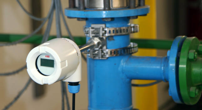
Why is a thermowell needed?
A bare temperature sensor inserted directly into a pressurised process would be exposed to forces it cannot withstand:
- High process pressure would push process fluid out through the sensor connection.
- High flow velocity would bend, erode or fatigue-fracture the sensor element within days or weeks.
- Corrosive or abrasive process fluids would chemically attack or physically abrade the sensor sheath.
- Replacing a bare sensor would require shutting down the process, depressurising the system and draining the pipe: an expensive and sometimes dangerous operation.
The thermo-well solves all four problems simultaneously. It takes the mechanical and chemical load on behalf of the sensor and allows the sensor to be swapped out in minutes while the process continues at full operating pressure and flow.
The Three Thermowell Stem Profiles
The stem (or shank) is the part-of-thermowell that extends into the process. There are three standard stem profiles, each representing a different engineering trade-off between response speed, mechanical strength and vibration resistance.
1. Straight Stem
- Uniform outer diameter from root (base) to tip
- Simplest and cheapest to manufacture
- Most robust profile. Heaviest wall thickness at the tip
- Slowest thermal response time of the three types
- Produces the highest drag force in high-velocity flow
- Best choice when the pipe bore limits the available diameter
- Not ideal for high-velocity applications due to vibration risk
2. Tapered Stem
- Diameter decreases from root to tip
- Most widely used stem type in oil and gas and chemical plants
- Better strength-to-weight ratio than straight
- Good vibration resistance due to varying diameter disrupting vortex formation
- Faster thermal response than straight (smaller tip diameter)
- Produces lower drag force than straight stem
- The ASME PTC 19.3 TW-1974 standard was specifically developed around tapered thermowells
3. Stepped Stem
- Larger diameter at the root, stepped down to a smaller diameter at the tip
- Combines the strength of the straight shank with the faster response of a small tip
- Best thermal response time of the three profiles
- Least robust profile at the step junction under cyclic loading
- Produces the lowest drag force of the three types
- Used in standard duty applications where fast response is more important than maximum strength
4. Twisted Square (Patented)
- Patented Rosemount Emerson design
- Square cross-section twisted along its length
- Physically disrupts Von Karman vortex formation
- Allows longer insertion lengths at higher flow velocities than any standard profile
- Used in high-velocity and high-accuracy control applications
- More expensive than standard profiles
| Stem profile | Thermal response | Mechanical strength | Vibration resistance | Drag force | Best for |
|---|---|---|---|---|---|
| Straight | Slowest | Highest | Moderate | Highest | Low-velocity flows, short insertion, budget applications |
| Tapered | Good | Good | Best (standard) | Moderate | General industrial use. Most widely specified type. |
| Stepped | Fastest | Lowest at step | Moderate | Lowest | Fast response needed; standard duty; lower velocity |
The Emerson Rosemount thermowell product range, one of the most widely used globally, covers all three stem profiles in threaded, flanged and welded configurations. See the Emerson Rosemount thermowell selection guide for technical specifications across each stem type and process connection style.
The Four Process Connection Types
The process connection is how the thermowell attaches to the pipe or vessel wall. There are four standard connection types, each suited to different pressure ratings, maintenance requirements and material constraints.
| Connection type | How it works | Typical pressure range | Key advantage | Key limitation |
|---|---|---|---|---|
| Threaded | Thermowell screws into a threaded nozzle or boss welded onto the pipe or vessel. Most commonly NPT or BSP thread. | Up to Class 600 / 100 bar typical | Easiest installation and removal. Can be replaced without welding. | Thread can corrode or seize. Not suitable for the highest pressure or toxic/lethal service without process isolation. |
| Flanged | Thermowell has a flange that bolts to a mating flange on the process nozzle. Standard ANSI / ASME or EN 1092 flange ratings apply. | Class 150 to Class 2500 / up to 420 bar | Handles the highest pressures. Easy replacement without hot work. Suitable for toxic and lethal service. | More expensive. Larger physical size. Requires mating flange on vessel or pipe. |
| Socket Weld / Weld-in | Thermowell is permanently welded directly into the pipe or vessel nozzle. No threaded joint or flange gasket. | All pressures. Limited only by the pipe and vessel rating | Most secure and leak-proof. No gasket to fail. No thread to corrode. Required for high-pressure, high-temperature or toxic service. | Cannot be removed without cutting. Requires a hot work permit and certified welder for replacement. Not for services requiring frequent sensor changes. |
| Van Stone (Lap Joint) | Two-piece design: the thermowell stem is made from exotic or corrosion-resistant material; the flange (lap ring) is made from lower-cost carbon steel. The ring can rotate to align bolt holes. | Up to Class 600 typical | Ideal when the process requires exotic material (Hastelloy, Titanium) for the wetted parts but carbon steel is acceptable for the flange. Significant cost saving over a solid exotic flange. | The interface between the stem and lap ring can be a weak point. Requires care during installation to ensure the lap ring seats correctly. |
Thermowell Key Dimensions Explained
Every thermowell datasheet or specification document will refer to three key dimensions. Understanding these is essential for ordering the correct thermowell and for calculating insertion depth.
| Dimension | Name | What it means | Selection rule |
|---|---|---|---|
| U-length | Insertion length | The distance from the process connection face (or root of thread) to the tip of the thermowell. This is how far the thermowell penetrates into the pipe or vessel. | The tip should reach at least the centreline of the pipe for the most representative measurement. Minimum: tip must extend past the pipe wall insulation boundary. Check wake frequency calculation for the chosen U-length. |
| T-length | Lagging extension | The distance between the process connection and the instrument connection at the top. This extension allows for pipe insulation or lagging to be applied without covering the instrument head connection. | Match to the insulation thickness specified for that line. Standard values: 0 mm (no insulation), 75 mm, 150 mm and 200 mm are most common. |
| Root diameter | Base diameter | The outer diameter of the thermowell at the process connection point. The root diameter is the strongest point of the thermowell. | Larger root diameter increases natural frequency and reduces vibration risk. Key parameter in ASME PTC 19.3 TW calculations. |
| Tip diameter | End diameter | The outer diameter at the tip of the thermowell. In tapered thermowells the tip is smaller than the root. | Smaller tip diameter improves thermal response time. Larger tip diameter reduces vortex shedding frequency. Both must be balanced against the wake frequency ratio. |
| Bore | Inner bore diameter | The inner diameter of the thermowell cavity. Must be large enough to accept the temperature sensor sheath or stem. | Standard bore sizes: 6.35 mm (0.25 inch) and 9.7 mm (0.385 inch). Match to the sensor stem diameter specified in the instrument datasheet. |
Von Karman Vortex Shedding: Why It Can Destroy a Thermowell
This is the most technically important topic in thermowell design and the one most often overlooked in routine projects. Getting it wrong can result in catastrophic thermowell failure in high-velocity process lines.
What is vortex shedding?
When a fluid flows past any cylindrical object (like a thermowell stem), the flow does not pass cleanly around both sides simultaneously. Instead, the boundary layer on each side separates alternately, creating a series of rotating vortices on the downstream side. This pattern of alternating vortices is called the Von Karman vortex street.
Each time a vortex is shed from one side of the thermowell, it creates a transverse force (a push sideways) on the stem. This force alternates from side to side at a frequency called the wake frequency or vortex shedding frequency. The wake frequency is calculated using the Strouhal number:
fw = St × V / d
Where: fw = vortex shedding frequency (Hz) | St = Strouhal number (approximately 0.22 for a cylinder) | V = fluid velocity (m/s) | d = thermowell tip diameter (m)
Higher velocity or smaller tip diameter = higher wake frequency. Higher wake frequency = greater vibration risk.
What is resonance and why is it dangerous?
Every thermowell has a natural frequency determined by its material, dimensions and insertion length. If the wake frequency from vortex shedding approaches or matches the thermowell's natural frequency, resonance occurs. During resonance, the amplitude of vibration grows rapidly. What started as small vibrations become large oscillations within seconds. The thermowell experiences rapidly escalating bending stress at the root and will suffer a fatigue fracture in a very short time. When a thermowell fails in a pressurised process line, the consequences can be severe: process fluid release, injury to personnel and environmental impact.
For a detailed technical reference on wake frequency calculation methodology, the Ashcroft thermowell wake frequency guide is an excellent field reference from a 40-year industry veteran. The Control and Instrumentation thermowell wake frequency page also includes a free online calculator.
How to prevent resonance: ASME PTC 19.3 TW
The ASME PTC 19.3 TW-2016 standard (Performance Test Code, Thermowells) is the internationally recognised standard for thermowell vibration analysis. It defines the calculation methods to verify that a thermowell will not experience resonance or fatigue failure in a given application. The standard requires:
- The frequency ratio (wake frequency / natural frequency) must be less than a defined safety limit (typically below 0.80)
- The bending stress from static flow forces must be within the material fatigue limit
- The in-line resonance condition (at half the transverse resonance velocity) must also be checked
Solutions when a thermowell fails the wake frequency calculation
| Solution | Effect | Most effective? |
|---|---|---|
| Shorten the insertion length (U-length) | Increases the natural frequency of the thermowell. The single most effective solution recommended by ASME PTC 19.3 TW-2016. | Yes: most effective |
| Increase root diameter | Increases natural frequency by adding stiffness at the base. Increases bending resistance. | Very effective |
| Increase tip diameter | Reduces vortex shedding frequency by increasing the tip diameter term in the Strouhal equation. | Moderately effective |
| Use a tapered stem instead of straight | Tapered profile provides better natural frequency characteristics and lower drag compared to straight at the same U-length. | Moderately effective |
| Use helical strakes (ScrutonWell® design) | Helical fins wound around the stem physically break up the coherent Von Karman vortex street, reducing oscillation amplitude by over 90%. Used only when geometry changes alone cannot solve the problem. | Highly effective for extreme cases |
| Relocate to a lower-velocity point in the pipe | Measures the same fluid at a point of lower flow velocity, reducing the wake frequency directly. | Situational |
Thermowell Materials: How to Select the Right One
The thermowell material must be compatible with the process fluid, withstand the maximum operating temperature and pressure, and resist any corrosion, erosion or chemical attack present in the process. The thermowell is a pressure vessel fitting and its material selection is as important as that of the pipe or vessel itself.
| Material | Max temperature | Best for | Avoid when |
|---|---|---|---|
| 316L Stainless Steel | Up to 900°C | Water, steam, general chemicals, most process fluids. The most widely used thermowell material globally. | Chloride environments (risk of stress corrosion cracking). Concentrated hydrochloric or sulphuric acid. |
| 304 / 304L Stainless Steel | Up to 870°C | General service where 316L is not required. Slightly lower corrosion resistance than 316L. | Same as 316L. Less preferred for process applications. 316L is the standard first choice. |
| Inconel 600 / 625 | Up to 1,093°C | High-temperature service, combustion gases, superheated steam, nuclear applications. Excellent oxidation resistance. | Reducing sulphur atmospheres at high temperatures. High cost limits use to demanding applications. |
| Hastelloy C-276 | Up to 1,038°C | Highly corrosive environments: hydrochloric acid, sulphuric acid, chlorine, seawater. Excellent resistance to pitting and crevice corrosion. | Cost is high. Oxidising acids at elevated temperatures. |
| Monel 400 | Up to 480°C | Seawater service, hydrofluoric acid, alkalis. Good resistance to reducing environments. | Oxidising acids. Not suitable for high-temperature applications. |
| Titanium | Up to 315°C | Extremely corrosive environments: wet chlorine, chlorinated solvents, seawater, nitric acid. Very low density. | Fluorine gas, concentrated sulphuric acid, dry chlorine. Brittle at very low temperatures. |
| Carbon Steel | Up to 425°C | Non-corrosive fluids, dry gas, oil where corrosion is not a concern. Lower cost. | Water, steam, acids or any wet service. Carbon steel will corrode rapidly in most process environments. |
Thermowell Selection Guide: Step by Step
- Step 1: Identify process conditions. Obtain the maximum operating pressure, maximum operating temperature, fluid type and density, maximum flow velocity and pipe internal diameter. These are the inputs for every selection decision.
- Step 2: Choose the material. Match the thermowell material to the process fluid using a corrosion compatibility table. If in doubt, consult a materials engineer. For most water, steam and general chemical service, 316L stainless steel is the correct first choice.
- Step 3: Choose the connection type. Threaded for general service up to Class 600. Flanged for higher pressure or where frequent removal is required. Weld-in for lethal, toxic or highest-pressure service.
- Step 4: Determine the required insertion length (U-length). Target the centre of the pipe as a starting point. Use at least 50% of the pipe internal diameter as minimum insertion. Then check the wake frequency calculation with this U-length.
- Step 5: Run the wake frequency calculation. Use the ASME PTC 19.3 TW-2016 method. Use the free Emerson or WIKA online calculators for the initial check. If the thermowell fails, adjust the U-length, root diameter or stem profile and recalculate.
- Step 6: Choose the stem profile. Tapered for most applications. Stepped where the fastest possible response time is the priority. Straight only when the pipe bore restricts the outer diameter or cost is the primary constraint.
- Step 7: Specify lagging extension (T-length). Match to the specified insulation thickness for that pipe or vessel. Standard values are 0 mm, 75 mm, 150 mm and 200 mm.
- Step 8: Specify the bore size. Match to the temperature sensor stem diameter. Confirm with the sensor supplier. Standard bores are 6.35 mm (1/4 inch) and 9.7 mm (3/8 inch).
For a comprehensive thermowell sizing tool that automates ASME PTC 19.3 TW calculations, the Emerson Rosemount Thermowell Design Accelerator is free to use and reduces calculation time from 50 hours to approximately 15 minutes per project. The WIKA web-based wake frequency calculator is another free tool covering all stem profiles within ASME PTC 19.3 TW-2016.
Common Thermowell Mistakes to Avoid
| Mistake | What happens | How to avoid it |
|---|---|---|
| Insufficient insertion length | The thermowell tip sits in the pipe wall boundary layer. Temperature reading is 5 to 15°C lower than the actual bulk fluid temperature. Control loops run inefficiently. | Always check that the U-length places the tip at or past the pipe centreline. On pipes below DN50 (2 inch), this may require an angled installation. |
| No wake frequency calculation performed | Thermowell fails by fatigue fracture in a high-velocity process line. Process fluid release. Loss of containment. | Always run an ASME PTC 19.3 TW calculation before ordering any thermowell that will be installed in a flowing process line. Use the free online tools from Emerson or WIKA. |
| Wrong material for the process fluid | Thermowell corrodes and thins rapidly. Eventually fails under process pressure, creating a leak. | Consult a corrosion compatibility table for every new fluid service. Never assume that 316L stainless steel is suitable for every application. |
| Sensor bore too small for the sensor | The temperature sensor cannot be inserted into the thermowell. Sensor must be returned to the supplier or the thermowell must be replaced. | Always confirm the thermowell bore size against the temperature sensor stem outer diameter before ordering. Allow a small clearance for thermal expansion. |
| Missing or wrong spring-loaded mechanism inside thermowell | The temperature sensor rattles inside the thermowell bore. Air gap between sensor tip and thermowell tip increases thermal resistance and slows response time. | Use a spring-loaded thermocouple or RTD assembly that maintains contact between the sensor tip and the thermowell tip under all operating conditions. |
Further Reading and External Resources
- Emerson Rosemount: Thermowell Portfolio and Design Accelerator. Free online thermowell sizing tool with ASME PTC 19.3 TW calculations from one of the world's leading temperature measurement manufacturers.
- WIKA: Thermowells and Protection Tubes. Complete thermowell product range overview from WIKA including technical selection criteria and the free online wake frequency calculator.
- Control Engineering: Taking the Mystery Out of Thermowell Selection. Practical thermowell selection guide from a leading process control industry publication.
- Omega Engineering: Thermowell Characteristics and Selection Criteria. Detailed technical reference on bore sizes, insertion lengths, materials and connection types.
Frequently Asked Questions: Thermowells
- What Is a Thermocouple and How Does It Work?
- Thermocouple Types: J, K, T, E, N, S, R and B Full Comparison
- RTD Sensor Connections: 2-Wire, 3-Wire and 4-Wire Explained
- How to Calibrate a Temperature Transmitter: Step-by-Step Procedure
- Cold Junction Compensation in Thermocouples Explained
- Common Temperature Measurement Errors and Their Causes
- Burnout Function in Temperature Transmitters Explained
What we learn today
- A thermowell is a closed-end metal tube that protects temperature sensors from process pressure, corrosive fluids and high flow velocity, while allowing sensor replacement during live process operation without a shutdown.
- There are three stem profiles (straight, tapered, stepped) and four process connections (threaded, flanged, weld-in, Van Stone). Tapered stem with flanged or threaded connection is the most commonly specified combination for general industrial use.
- Von Karman vortex shedding creates alternating forces on the thermowell stem. If the wake frequency matches the thermowell's natural frequency, resonance occurs and the thermowell can fail by fatigue fracture. Every thermowell in a flowing line must be checked using ASME PTC 19.3 TW-2016.
- The U-length (insertion length) must place the tip at or beyond the pipe centreline for a representative measurement. Shortening the U-length is the most effective way to prevent vortex-induced resonance when a thermowell fails the wake frequency calculation.