
A dial gauge can look perfectly healthy while its pointer quietly reads a few percent high after years of vibration and pressure cycles. A disciplined pressure gauge calibration with the right reference, the right test points and honest records tells you exactly how much you can trust it.
Mechanical pressure gauges drift with vibration, overpressure and age, so pressure gauge calibration against a better reference is needed at regular intervals. This guide explains the equipment, the test sequence, the error and hysteresis maths and the pass or fail decision.

What Is Pressure Gauge Calibration?
Pressure gauge calibration is the documented comparison of a gauge reading against a reference standard of known and better accuracy, at several points across the scale, to find its error. Most plant gauges are Bourdon tube pressure gauges, whose curved tube, link and gear sector wear and relax over time.
Calibration by itself only measures the error. Adjustment is a separate action taken when the error is outside tolerance, and the terms as found, as left and correction are explained in instrument calibration common terms.
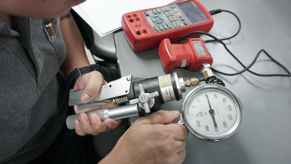
A good result depends on three things: a reference that is traceable to national standards, a sensible sequence of test points, and careful reading of the pointer. The accuracy class printed on the dial, covered in pressure gauge accuracy classes, sets the tolerance you test against.
Why Dial Gauges Drift in Service
Pulsating pumps, compressor discharge and water hammer keep the movement in constant motion, which wears the pinion teeth and loosens the pointer. The damage caused by sudden surges is described in hammer effect in pressure gauges.
A Bourdon tube works because pressure tries to straighten its oval, curved cross section. The tip moves only a few millimetres at full scale, and the gear sector magnifies that tiny travel into a sweep of about 270 degrees.
Reference Equipment for the Test Bench
A hand pump with two ports holds the gauge under test and a reference gauge or module side by side.
Oil or water is pressurised with a screw piston, giving fine control at high pressure.
Known masses on a piston of known area generate a primary pressure, independent of any reference gauge.
A precision sensor with a display, often combined with a pump, logs readings electronically.
The dead weight method generates pressure from force divided by area, so its accuracy comes from the masses and piston rather than from another gauge. The working principle and gravity correction are explained in dead weight pressure tester.
For pressure gauge calibration, Fluke Calibration advises keeping a test accuracy ratio of about 4 to 1 between the reference and the device under test. Near the tolerance limit, a weaker ratio raises the risk of falsely accepting or rejecting a gauge.
For a class 1.0 gauge, choose a reference whose uncertainty is about 0.25 percent of the same span or better. A 0.05 percent digital module comfortably covers classes 1.0 and 0.6.
Accuracy Classes Under EN 837 and ASME B40.100
| Standard | Class or Grade | Permissible Error |
|---|---|---|
| EN 837 1 | 0.1, 0.25, 0.6 | Test and reference gauges, percent of span |
| EN 837 1 | 1.0, 1.6 | Common process gauges, percent of span |
| EN 837 1 | 2.5, 4.0 | Utility and general service gauges |
| ASME B40.100 | Grade 4A, 3A, 2A | 0.1, 0.25 and 0.5 percent of span |
| ASME B40.100 | Grade 1A | 1 percent of span over the full scale |
| ASME B40.100 | Grade A | 2 percent, 1 percent in the middle half, 2 percent |
Under EN 837 the class number is the maximum permissible error as a percentage of the span, so a class 1.6 gauge of 0 to 10 bar may be off by 0.16 bar anywhere on the scale. The pressure gauge selection factors guide shows how class, range and size are chosen together.
9 Steps of a Practical Pressure Gauge Calibration
Tameson recommends exercising the gauge at pressure for about one minute and releasing it, repeated two or three times before readings are taken. This settles friction in the movement and gives more repeatable results.
Never overshoot a test point and then come back to it, because that mixes the rising and falling curves and hides hysteresis. Pointer reading technique, parallax and resolution are part of the difference between accuracy and precision that a careful technician respects.
DKD R 6 1 Calibration Sequences
| Sequence | Gauge Accuracy | Points | Series | Preloads |
|---|---|---|---|---|
| A | Better than 0.1 percent | 9 minimum | 2 up, 2 down | 3 |
| B | 0.1 to 0.6 percent | 9 minimum | 2 up, 1 down | 2 |
| C | Worse than 0.6 percent | 5 minimum | 1 up, 1 down | 1 |
The guideline also asks for a waiting time of at least 30 seconds after each load change and a hold at the upper limit of 2 minutes, or 5 minutes for Bourdon tube gauges. Most class 1.0 and 1.6 plant gauges fall under sequence C, the usual pressure gauge calibration routine in process plants.
Pressure Gauge Calibration Error Formula
For each point, the error is the gauge reading minus the reference value, and it is normally expressed as a percentage of span. The same thinking about zero and span error appears in offset, zero point and span error.
Hysteresis % = |Falling reading minus Rising reading| ÷ Span × 100
Example, gauge 0 to 10 bar, class 1.0:
Reference 6.00 bar, rising reading 6.04 bar, falling reading 6.09 bar
Rising error = 0.04 ÷ 10 × 100 = 0.40 %
Falling error = 0.09 ÷ 10 × 100 = 0.90 %
Hysteresis = 0.05 ÷ 10 × 100 = 0.50 %
Largest value 0.90 % is within the 1.00 % limit, so PASS
Gauge Error and Hysteresis Calculator
Second Worked Example: A Gauge Reading High
A 0 to 25 bar class 1.6 gauge on a boiler feed pump has a permissible error of 0.016 × 25 = 0.40 bar. At the 20 bar test point it reads 20.50 bar rising and 20.60 bar falling, giving errors of 2.0 and 2.4 percent.
Both values exceed 1.6 percent, so the as found result is FAIL and the gauge must be adjusted or replaced. If the zero is correct and the error grows with pressure, the span is at fault and the link position on the sector needs correcting.
Adjusting Zero and Span on a Bourdon Gauge
Zero error, where every point is off by the same amount, is corrected by resetting the pointer or turning the micro zero screw found on many gauges. Span error, where the error grows with pressure, is corrected by moving the link along the slotted sector arm.
Always correct span first and zero second, then repeat both until they stop interacting. Mark the pointer position before removing it so that you never lose the original setting.
Liquid Head and Other Error Sources
When a hydraulic comparator is used, any height difference between the gauge and the reference adds a liquid column pressure of density × g × height. With water and a 0.5 m difference this is 1000 × 9.81 × 0.5 = 4905 Pa, about 0.05 bar.
Pressurising air quickly heats it and then it slowly cools, so the reading drifts down for a short time after each step. This adiabatic effect is one reason DKD R 6 1 asks for at least 30 seconds before a reading.
Pressure Gauge Calibration Troubleshooting Checklist
- Reading drifts at a steady point: check for leaks at fittings and the pump.
- Large tapped versus untapped difference: suspect worn gears or a dry pivot.
- Error same at every point: correct zero by resetting the pointer.
- Error grows with pressure: adjust the span link on the sector.
- Pointer sticks or jumps: inspect for bent pointer or glass contact.
- Readings differ by position: calibrate in the same orientation as in service.
- Liquid filled gauge reads high when warm: vent the case to release trapped pressure.
- Confirms readings used for safety and quality decisions.
- Detects overpressure damage and worn movements early.
- Gives traceable evidence for audits and ISO 9001.
- Builds a history that sets smarter calibration intervals.
- Takes the gauge out of service during the check.
- Comparators add their own uncertainty to the result.
- Low cost gauges may cost more to repair than to replace.
- A pass today does not prevent tomorrow's overpressure.
Records, Certificates and Calibration Intervals
A pressure gauge calibration certificate should state the reference used, its traceability, the ambient conditions, the as found and as left data and the uncertainty of the result. Laboratories accredited to ISO 17025 follow the rules in ISO 17025 calibration laboratory requirements.
Tameson suggests at least annual pressure gauge calibration, with shorter intervals for gauges in harsh service. A history based method for setting the period is described in calibration interval determination.
The uncertainty statement combines the reference uncertainty, reading resolution, repeatability and hysteresis. The method is explained in measurement uncertainty in calibration.
Guideline DKD R 6 1 From PTB
Hand Pump Calibration Demonstration
Pressure Gauge Calibration FAQ
It is a documented comparison of a gauge against a traceable reference at several points across the scale. The result shows the error at each point and whether the gauge meets its class.
Adjustment is a separate step taken only when the error is too large. The as found and as left readings are both recorded for the history file.
Most process gauges are checked at 0, 25, 50, 75 and 100 percent of the scale, both rising and falling. This matches the minimum of 5 points in DKD R 6 1 sequence C of the guideline.
High accuracy test gauges need at least 9 points and more cycles. Sequences A and B cover gauges of 0.6 percent class and better.
A mechanical movement has friction and elastic lag, so readings approached from below and from above differ. That difference, measured at the same test point, is the hysteresis of the gauge.
A rising run alone hides this error completely, however carefully it is performed. Worn gauges with loose gears often pass on the way up yet fail on the way down.
The reference should be traceable and roughly four times more accurate than the gauge under test. Fluke Calibration notes that this ratio limits false accept and false reject decisions.
A dead weight tester suits laboratory work and precision gauges. A hand pump with a digital module suits routine field checks of class 1.0 and 1.6 gauges.
Subtract the reference value from the gauge reading, divide by the span and multiply by 100. The largest value at any point is compared with the class.
For a 0 to 10 bar class 1.0 gauge, a reading of 6.09 bar at 6.00 bar is 0.90 percent. That is inside the 1.00 percent limit, so it passes.
A light tap frees the gear train from small static friction before each reading. It gives the value the gauge would show on a normally vibrating process line.
Record both tapped and untapped readings whenever your written procedure requires it. A large difference between them signals a worn, dry or dirty movement that needs service.
Tameson suggests at least once a year, with shorter intervals for harsh, pulsating or safety related service. The right interval really depends on the as found history of each tag.
If a gauge is repeatedly found in tolerance, the interval can be extended with recorded evidence. Repeated failures call for a shorter interval, better protection or a better gauge.
Related Articles
- Dead Weight Pressure Tester
- Pressure Gauge Accuracy Classes
- Bourdon Tube Pressure Gauges
- Measurement Uncertainty in Calibration
- How to Calibrate a Pressure Sensor
External References
- Guideline DKD R 6 1, Calibration of Pressure Gauges, PTB
- Pressure Gauge Calibration, Tameson
- Deadweight Tester, Wikipedia
What We Learn Today
- Pressure gauge calibration compares the gauge with a traceable reference at rising and falling points, usually 0, 25, 50, 75 and 100 percent of span.
- Error is the reading minus the reference divided by span, and hysteresis is the gap between falling and rising readings at the same point.
- Use a reference about four times better than the gauge, exercise it before testing, tap lightly, and keep both gauges at the same height.