
Most bad pH readings come from a few repeat causes such as a coated glass bulb, a clogged reference junction or a poor cable earth. This guide shows how to read slope, offset and impedance numbers so you fix the real fault instead of recalibrating again and again.
pH sensor troubleshooting starts with the slope, offset and response time you see during a two buffer calibration. This guide gives the limits, a fault table, cleaning steps, a slope calculator and a solved example.
What Is pH Sensor Troubleshooting?
pH sensor troubleshooting is the step by step process of finding why an online pH loop reads wrong, slow or unstable, by checking the electrode slope, offset, response time and reference impedance against known limits. It separates sensor faults from transmitter, cable and process problems before anyone replaces an expensive pH electrode.
- A perfect electrode gives 59.16 mV per pH at 25 °C and 0 mV in pH 7 buffer.
- A new electrode shows a slope in the upper 90s percent.
- Replace the electrode when the slope falls to the mid or low 80s percent.
- An offset of 30 mV or more means about 0.5 pH error and points to the reference.
- A response slower than about 120 seconds means the probe needs cleaning or replacement.
Every pH electrode ages from the day it is installed, so the goal is not a perfect sensor. The goal is to know when cleaning is enough and when replacement is the cheaper option.
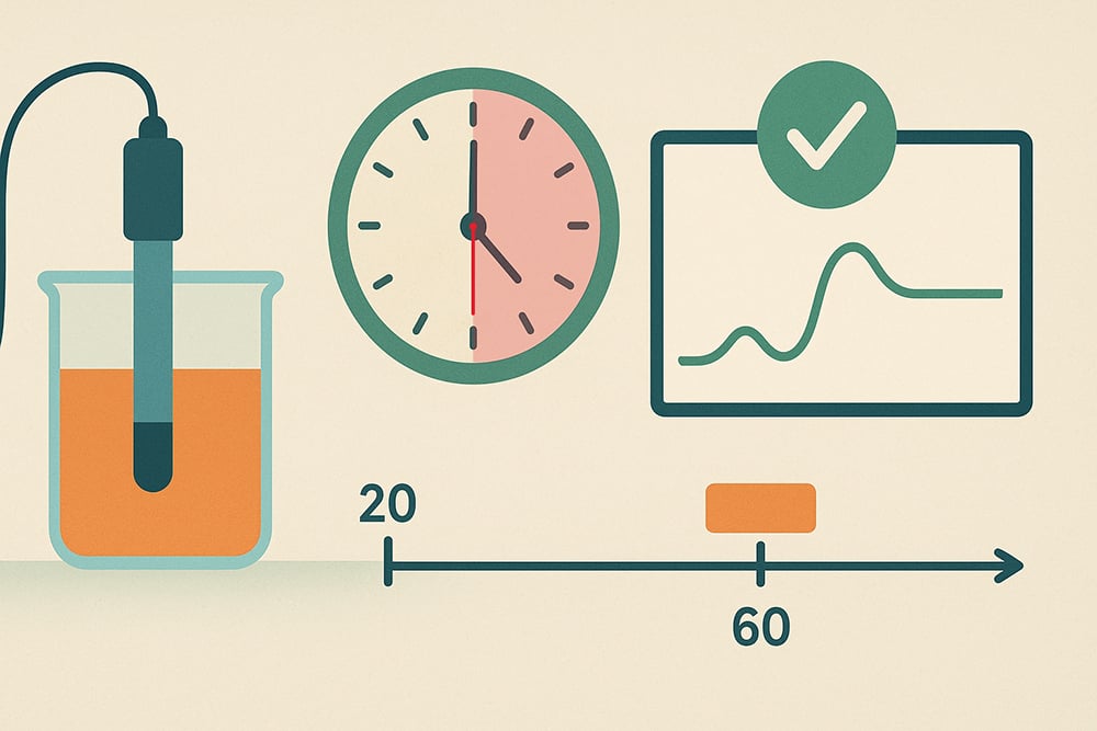
Yokogawa notes that a reading within ±0.1 pH per instrument is normally acceptable, and that you should start troubleshooting when the total uncertainty passes ±0.2 pH. Keep that tolerance in mind, together with the basics of measurement uncertainty, before you chase small differences against a lab meter.
pH Sensor Troubleshooting Table: Symptoms and Fixes
Use this pH sensor troubleshooting table as the first screen in the field. It links each common symptom to its most likely cause and the quickest check.
| Symptom | Likely cause | Quick check | Fix |
|---|---|---|---|
| Slow response | Coated or dehydrated glass bulb | Response time in buffer | Clean, soak, recalibrate |
| Slow upward drift | Clogged or poisoned reference junction | Reference impedance | Clean junction or replace sensor |
| Low slope | Aged or coated glass | Slope after two buffer calibration | Clean in dilute acid, then replace |
| Large offset | Contaminated reference electrolyte | mV in pH 7 buffer | Replace reference or sensor |
| Noisy reading | Ground loop, wet cable, poor shield | Reading with sample isolated | Fix earthing and cable |
| Stuck reading | Cracked bulb or shorted cable | Glass impedance alarm | Replace sensor or cable |
| Value differs from lab | Temperature or sample handling | Compare at 25 °C | Correct the method, not the sensor |
Notice that two of the seven rows are not sensor faults at all. A wet cable or a ground loop can mimic a failing electrode perfectly.
Before any pH sensor troubleshooting repair, write down the current slope, offset and impedance from the transmitter. Those numbers tell you whether the next cleaning actually helped.
pH Electrode Slope and Offset Limits
Slope is the electrode efficiency compared with the ideal Nernst value, and offset is the millivolt output in pH 7 buffer. The pH sensor troubleshooting limits below combine figures published by Yokogawa and PIE Calibrators.
| Parameter | Healthy | Watch or clean | Replace |
|---|---|---|---|
| Slope (Yokogawa) | Upper 90s % when new | Falling trend | Mid to low 80s % |
| Slope (PIE Calibrators) | 85 to 102 % | Near 85 % | Outside 85 to 102 % |
| Offset in pH 7 buffer | Near 0 mV, a few mV when new | Rising trend | ±30 mV (Yokogawa), ±50 mV (PIE) |
| Reference impedance | Below 10 to 15 kΩ | 30 to 35 kΩ, drift starts | Alarm above 100 kΩ |
| Response time | 30 to 60 s | 60 to 120 s | Over 120 s (PIE Calibrators) |
Low conductivity water is a special case, and Yokogawa notes that reference impedance of 200 to 500 kΩ is not uncommon there. Check the sample conductivity before you trust an impedance alarm.
At 25 °C, one pH unit equals 59.16 mV, so a 30 mV offset already means about half a pH unit of error. That is why offset limits are tighter than they look.
Slope and Offset Formula With Solved Example
The slope is the measured millivolt change between two buffers divided by the theoretical change. The theoretical value grows with temperature at 0.1984 mV per pH per kelvin.
At 25 °C: 0.1984 × 298.15 = 59.16 mV/pH
Buffer 7 reads 12 mV, so offset = 12 mV
Buffer 4 reads 170 mV
Measured change = 170 minus 12 = 158 mV over 3 pH
Slope = 158 ÷ (3 × 59.16) × 100 = 89.0 %
Offset error = 12 ÷ 59.16 = 0.20 pH
Verdict: usable, clean and recalibrate, then watch the trend
Run the same calculation after every calibration and plot it, because a falling slope trend predicts failure weeks ahead. Many smart transmitters store these values and report them over HART.
pH Probe Slow Response
In pH sensor troubleshooting, a slow probe is the classic symptom of a coated or dried out glass bulb. PIE Calibrators gives 30 to 60 seconds as a typical settling time and treats more than 120 seconds as a sign that the probe needs reconditioning or replacement.
Yokogawa adds that a sensor left dry for 12 hours or more, on a bench or in an empty tank, needs a soak before use. Soak for about 30 minutes after a short dry spell and up to 24 hours in severe cases, in pH 4 or 7 buffer, reference fill solution or tap water.
Match the cleaner to the coating: dilute acid for scale and hydroxides, a mild detergent for oil and grease. After any chemical cleaning, a fresh calibration is not optional.
pH Sensor Drift and Reference Junction Clogging
Good pH sensor troubleshooting treats slow drift in one direction as a reference problem first, not a glass problem. Yokogawa explains that upward drift begins as the reference impedance approaches 30 to 35 kΩ, and that sulfide deposits typically show up in the 30 to 45 kΩ band.
Atlas Scientific calls the clogged junction the most common cause of drift in glass electrodes, often from silver salts or heavy metals. Process pressure above one atmosphere can also force process liquid into the reference, so check the process pressure and temperature at the mounting point.
Glass and reference in one body with a porous junction. Cheap and common, but the junction clogs in dirty samples.
A second salt bridge protects the inner reference from poisoning ions such as sulfide.
Uses a second glass electrode as reference with a solution ground, reducing junction and ground loop errors.
A dry glass membrane cannot respond properly because the hydrated gel layer is what senses hydrogen ions. Yokogawa even describes reviving dried sensors by heating to 80 °C in electrolyte and cooling them slowly.
Noisy pH Readings, Ground Loops and Cable Faults
The glass membrane has a very high resistance, so its signal cable acts like an antenna. Yokogawa states that cable isolation must exceed 1,000 times the glass membrane resistance, which is why wet connectors cause wild readings and why shielded low noise cable is used.
A simple pH sensor troubleshooting trick helps here: a noisy reading that settles when you lift the sensor into a beaker of buffer points to a ground loop through the process. Fix it with a solution ground, an isolated transmitter input and proper earthing practice rather than heavier damping.
Separate the Sensor From the Transmitter
PIE Calibrators recommends this simulator check as an early pH sensor troubleshooting step, with temperature compensation off or fixed at 25 °C. If the transmitter passes, the fault is in the sensor, while a failure points to the input card or the 4 to 20 mA loop, which a multifunction calibrator can confirm.
pH Sensor Myths in the Field
Preventive pH Sensor Checklist
- Record slope, offset and impedance after every calibration
- Use fresh, in date buffers at the same temperature as the sensor
- Keep the glass wet during shutdowns and storage
- Clean before calibrating, never the other way round
- Inspect cable glands and connectors for moisture
- Confirm the solution ground and shield earth at one point only
- Compare with a lab sample cooled to 25 °C
A routine like this turns pH sensor troubleshooting into a planned job instead of an emergency. Set the interval using your own history, as described in our note on calibration interval determination.
Automatic Sensor Diagnostics: Worth It?
- Slope, offset and impedance are tracked without a site visit.
- Impedance alarms flag cracked glass or a clogged junction early.
- Trends show when cleaning is due.
- Less guesswork during pH sensor troubleshooting.
- Alarm limits need tuning for low conductivity water.
- Diagnostics cannot detect a coating that has not yet slowed response.
- Some older transmitters do not support them.
- They still need a person to act on the alarm.
Troubleshooting pH Instruments PDF
Video on pH Meter Troubleshooting
pH Sensor Troubleshooting FAQ
The most common causes are a coated glass bulb, a clogged reference junction and old or contaminated buffers. A wet cable or ground loop can also shift the reading.
Start with a fresh two buffer calibration and note the slope and offset. Those two numbers usually tell you which part of the system is at fault.
A new electrode usually shows a slope in the upper 90s percent of the ideal 59.16 millivolts per unit at 25 degrees. PIE Calibrators accepts 85 to 102 percent as the working band.
Yokogawa advises replacing the electrode when the slope falls to the mid or low 80s. Cleaning can recover a coated sensor, but an aged glass membrane will not come back.
Slow drift in one direction usually comes from a clogged or poisoned reference junction. Sulfide, silver salts and heavy metals are frequent culprits in process streams.
Temperature changes and a slowly drying glass bulb can also cause drift. Checking the reference impedance on the transmitter is the fastest way to confirm the cause during pH sensor troubleshooting.
Rinse it in water, then soak it in a 5 to 10 percent hydrochloric acid solution for one to two minutes. Brush the glass gently with a soft brush and rinse it thoroughly.
Soak in water for two to three minutes so the glass rehydrates. Always recalibrate afterwards, because cleaning changes both the slope and the offset.
A slow probe usually has a coated, scratched or dried out glass bulb. A typical healthy probe settles in 30 to 60 seconds in a buffer.
If it takes more than about 120 seconds, clean and soak it first. When cleaning does not restore the speed, the electrode has reached the end of its life.
Check the slope, offset and response time after a careful two buffer calibration. A slope below about 85 percent or an offset beyond 30 millivolts are clear warning signs.
Also watch for a glass impedance alarm, which can mean a cracked bulb. If careful cleaning and soaking do not fix these numbers, replace the probe.
Yokogawa suggests that calibration should not be needed more often than once a month in typical general service. Dirty or hot processes may need shorter intervals.
Base the interval on your own slope and offset history. If a sensor needs calibration every few days, treat that as a fault to investigate rather than a schedule.
Related Articles
- What Is a pH Sensor and How It Works
- ORP Measurement Explained
- Conductivity Sensor Working
- Ground Loop Causes and Prevention
- Instrumentation Calibration and Troubleshooting Guide
External References
- Troubleshooting pH Instruments, PIE Calibrators
- Succeed at pH Troubleshooting, Yokogawa
- pH Meter, Wikipedia
What We Learn Today
- pH sensor troubleshooting starts with slope, offset and response time: a new electrode shows a slope in the upper 90s percent.
- An offset of 30 mV equals about half a pH unit at 25 °C and usually points to a poisoned or clogged reference junction.
- Use a pH simulator to separate the transmitter from the sensor, and fix noisy readings with proper earthing instead of extra damping.
