
Every transmitter, switch, analyser and control valve on a project starts life as a single row in one master list. That list feeds datasheets, I/O assignments, loop sheets and purchase orders, so a clean index saves weeks of rework later.
The instrument index is the master register of every tagged device on a plant, from the first P&ID to the as built handover. This guide explains its columns, tag numbering, links to other documents, database tools and a quick I/O card estimate.
What Is an Instrument Index?
An instrument index is a register that lists every tagged instrument on a project, one row per tag, with its service, range, signal type and references to its drawings and datasheets. The tags come from the piping and instrumentation diagram, so the index is the P&ID written out as a searchable table.
Greg McMillan, Mike Laspisa and Hunter Vegas, writing in Control Global, call it the backbone of the I&C engineering effort on any project. They note that what starts as basically a list of devices grows into a multi functional document as the project moves through its phases.

A tag such as PT 1101 may appear on ten documents, yet it is created only once, in the index. Engineers often call it the instrument list or tag register, and the short forms used on it are listed in instrumentation and automation abbreviations.
Where the Index Sits in the Design Document Chain
The instrument index is the parent of almost every other instrument deliverable. A tag added, deleted or changed on a P&ID is entered here first and then flows down.
Automation Forum lists the same links: P&IDs supply tags and services, datasheets hold the specification, and the I/O list contains only points wired to the DCS I/O cards.
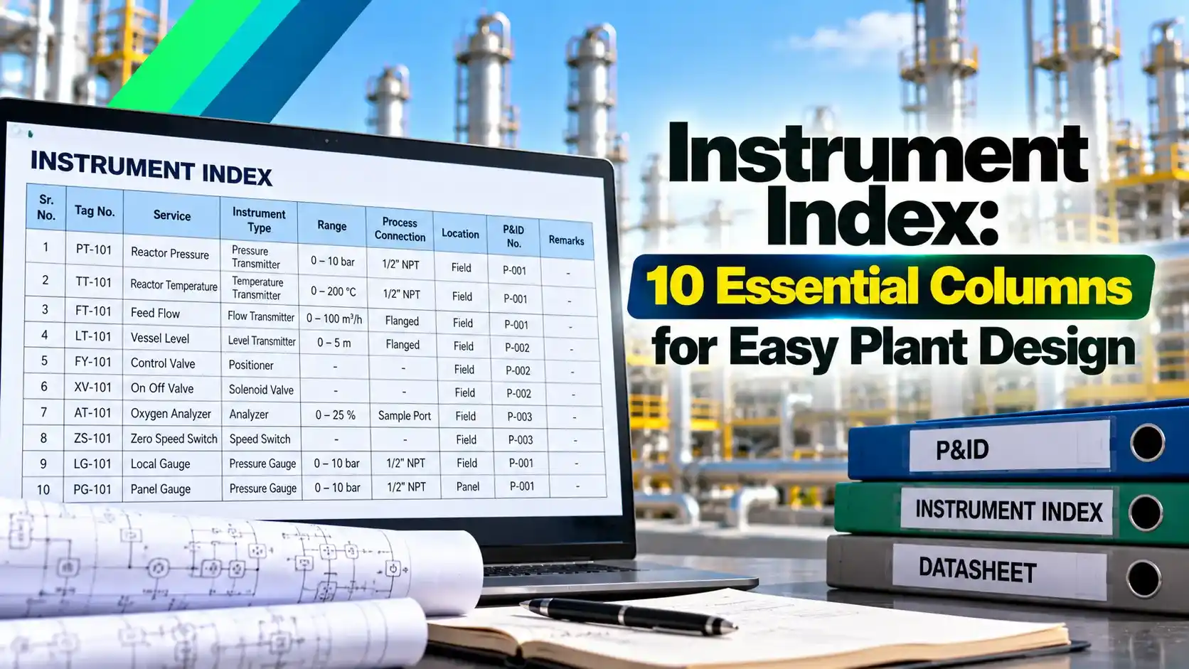
10 Essential Instrument Index Columns
These ten instrument index columns are the minimum most EPC contractors expect, and Pathnovo notes that a mature database can hold more than a hundred fields per tag. Common extras are hazardous area data, manufacturer, model and SIL rating.
The range column needs special care because it feeds transmitter configuration and DCS scaling. A smart transmitter can be reranged in minutes, but a wrong range here is copied into the datasheet and database before anyone notices.
Freeze the column list and its allowed values in a project procedure before the first issue. Free text in fields like instrument type or I/O type makes filtering and counting unreliable later.
How ISA 5.1 Tag Numbers Are Built
ANSI/ISA 5.1, Instrumentation Symbols and Identification, defines the tag used in every row, and its latest edition was published in 2024. A tag has a functional identification made of letters and a loop number, often with a plant area prefix.
| Part of Tag | Example | Meaning |
|---|---|---|
| Area or unit prefix | 21 | Plant area or unit 21 |
| First letter | F | Measured variable is flow |
| Succeeding letters | IC | Indicating controller |
| Loop number | 101 | Loop 101 in that area |
| Suffix | A or B | Separates duplicate devices in one loop |
| Complete tag | 21 FIC 101A | Flow indicating controller, loop 101, device A |
The first letter always names the measured or initiating variable, such as F for flow, L for level, P for pressure, T for temperature and A for analysis. The succeeding letters describe what the device does, such as T for transmit, I for indicate, C for control, S for switch, E for primary element and V for valve.
Every device in one loop shares the loop number, so FE 101, FT 101, FIC 101 and FV 101 form flow loop 101. Sorting the instrument index by loop number shows each loop as one block of rows.
Mike Laspisa, quoted in Control Global, prefers plain sequential loop numbers to smart numbers that encode physical location. Locations are often unknown when tagging starts, so smart numbers force rework later.
Instrument Index Versus I/O List and Datasheets
- Every tagged device, wired or not.
- Gauges, thermowells and orifice plates.
- One summary row per tag.
- References to other documents.
- Only points wired to a system.
- Rack, slot and channel detail.
- Full specification of one device.
- Process data and materials.
A local gauge, an orifice plate or a thermowell has a row in the index but no I/O point, so the I/O list is always shorter. The I/O list is then extended with the card data described in marshalling cabinet DCS wiring.
The datasheet, on ISA 20 style forms or the newer ISA TR20.00.01 templates, carries process conditions, materials and accessories. For a valve it records the control valve sizing results, while the index keeps only the tag and datasheet number.
I/O Count and Card Estimate From the Index
A complete index lets you count I/O points by type and estimate the control system cards needed. Designers first add installed spare capacity, commonly 10 to 20 percent as set by the project specification.
Cards per type = I/O with spare ÷ Channels per card, rounded up
Example, 16 channel cards, 20 percent spare:
AI: 120 × 1.2 = 144, cards = 144 ÷ 16 = 9
AO: 40 × 1.2 = 48, cards = 48 ÷ 16 = 3
DI: 150 × 1.2 = 180, cards = 180 ÷ 16 = 11.25, so 12
DO: 60 × 1.2 = 72, cards = 72 ÷ 16 = 4.5, so 5
Total 444 I/O with spare on 29 cards
The count is only as good as the I/O type column, so check that every 4 to 20 mA current loop device is marked AI or AO and every switch or solenoid DI or DO.
Instrument Index I/O Card Calculator
Worked Example: Adding a Package Unit
Suppose a vendor skid adds 36 AI, 10 AO, 44 DI and 18 DO to the same system with 20 percent spare and 16 channel cards. With spare this gives 44, 12, 53 and 22 points, a total of 131.
The cards needed are 3 AI, 1 AO, 4 DI and 2 DO, which is 10 more cards. If the cabinets have only six free slots, a new cabinet or remote I/O panel must be added to the scope.
Run the I/O count straight from the index after every revision and compare it with the last count. A sudden jump usually means a vendor package was merged in, or duplicate rows were created.
Building and Maintaining the Index Through a Project
Control Global describes this practice and says the change reports can support engineering change orders to the client.
During commissioning the index becomes the master record for the instrument loop checking procedure, with a status column showing tags installed, checked and handed over.
Tags in the index also become the point names in the control system, as covered in SCADA tag database design. When both use the same spelling, bulk configuration and the factory acceptance test run far more smoothly.
- Every P&ID tag bubble has one row in the instrument index.
- No duplicate tag numbers exist after a sort.
- Every wired device has an I/O type and system name.
- Ranges and units match the process data sheet.
- Deleted tags are flagged, not silently removed.
- The issue matches the latest P&ID revision.
Instrument Index Database Tools
Controlled Excel workbook with locked columns.
MS Access with forms and reports.
Intergraph Smart Instrumentation, formerly SmartPlant Instrumentation and INtools, or AVEVA Instrumentation.
Control Global lists three classic formats for an instrument index: a simple Excel workbook, a database such as MS Access, or relational database software that generates documents from tag data.
These figures come from the Hexagon brochure, where the instrument index module is the entry point for all tag data.
In a database tool the loop sheets, specification sheets and wiring reports are generated from the same tag record. Changing a range once in the index updates every document that shows it at the next issue.
Common Mistakes and How to Fix Them
The most common fault is a tag that is on the P&ID but missing from the index, usually a local gauge or vendor package device. A regular cross check between the two lists catches it.
Another problem is inconsistent I/O typing, such as a HART transmitter marked as fieldbus, which gives wrong card counts. The signal options are compared in how the HART protocol works.
Many brownfield sites also have an outdated instrument index that no longer matches the field. A walk down audit before a DCS migration rebuilds it tag by tag.
Instrument Index Reference Brochure
Instrument Index Video Lesson
Instrument Index FAQ
It is a table that lists every tagged instrument on a project, with one row for each tag. Each row holds the service, location, range, signal type and references to drawings and datasheets.
The tags come from the P&IDs, so the index is really the P&ID in a searchable form. Control Global calls it the backbone of the I&C engineering effort on any project.
The core set is tag number, service, P&ID number, line or equipment number and instrument type. Range, I/O type, datasheet number, drawing references and revision status complete the ten basic columns.
Large projects add many more fields, such as hazardous area data, manufacturer and model. Pathnovo notes that mature engineering databases can hold more than a hundred fields per tag.
The index contains every tagged device, including gauges, thermowells and orifice plates that have no electrical signal. The I/O list is a filtered subset that holds only the points wired to a control system.
The I/O list then adds rack, slot and channel data for each of those points. Both documents must use identical tag numbers, or loop checks and configuration will quickly go wrong.
ANSI/ISA 5.1, Instrumentation Symbols and Identification, defines the identification letters and loop numbers. Its latest edition was published in 2024 and is followed by most projects in India.
The first letter gives the measured variable and the following letters give the device function. An area prefix and a suffix letter are then added according to the project numbering convention.
The instrument design team of the EPC contractor prepares it from the issued P&IDs. Process, electrical and control system engineers then add their own data as the design develops.
At handover the plant owner receives the final as built version. Maintenance engineers keep it current afterwards through the site management of change procedure, so every field modification is recorded.
Control Global reports that plain sequential loop numbers are much easier to handle on real projects. Smart numbers that encode a physical location look neat but often need rework later.
Locations are usually unknown when tagging begins on the early P&IDs. Sequential numbering combined with a separate location column in the index avoids that problem completely.
Small jobs often use a controlled Excel workbook or an MS Access database with forms and reports. Large projects use engineering databases such as Intergraph Smart Instrumentation or AVEVA Instrumentation.
Smart Instrumentation was earlier known as SmartPlant Instrumentation and, before that, INtools. In these tools the index module feeds datasheets, loop sheets and wiring reports.
Related Articles
- Piping and Instrumentation Diagram
- Instrument Loop Checking Procedure
- DCS I/O Card Types Explained
- Marshalling Cabinet DCS Wiring
- SCADA Tag Database Design
External References
- Intergraph Smart Instrumentation Brochure, Hexagon
- Instrument Index Insights, Control Global
- Piping and Instrumentation Diagram, Wikipedia
What We Learn Today
- An instrument index lists every tagged device once, with service, range, I/O type, datasheet and drawing references, and it feeds every other instrument deliverable.
- ISA 5.1 tags combine a first letter for the measured variable, function letters and a loop number, and sequential loop numbers are easier to manage.
- Counting AI, AO, DI and DO from the index with 20 percent spare on 16 channel cards gives an early estimate of cards and cabinets.