
A motor bearing built to run for years can fail within months once a variable frequency drive starts feeding the motor. The culprit is a tiny electrical discharge through the grease film, repeated millions of times until the races are ruined.
VFD induced bearing currents are one of the most common hidden causes of repeat motor bearing failures. This guide explains where they come from, how to recognise the damage and which fixes actually work.
What Is Meant by VFD Bearing Currents?
VFD bearing currents are unwanted currents that flow from the motor shaft through the bearing balls and races to the motor frame. They are driven by the fast switching voltage of a PWM inverter, described in VFD working principle, and they do not occur in the same way on a sine wave mains supply.
In a mains fed AC induction motor, the three phase voltages add up to almost zero at every instant. An inverter switches each phase between the positive and negative DC bus, so the sum of the three output voltages is never zero, and this sum is called the common mode voltage.
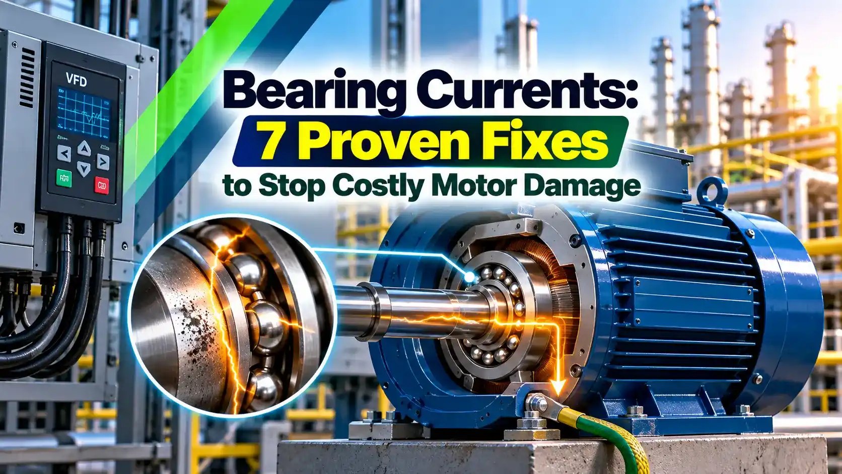
Industrial Equipment News reports that shaft voltages of 70 V peak to peak or more are easily measured on VFD driven motors with an oscilloscope probe. It also notes that bearings designed for 100,000 hours of life can fail within about one month of operation.
How Common Mode Voltage Reaches the Shaft
The switching edges come from the fast IGBT devices in the inverter bridge, with rise times well below one microsecond. For a 2 level inverter the common mode voltage steps between plus and minus half of the DC bus voltage, at the carrier frequency.
Inside the motor, the path for bearing currents is a network of small capacitors formed by the stator winding, the rotor and the frame. The winding to rotor capacitance couples part of the common mode voltage onto the rotor, while the rotor to frame and bearing capacitances divide it down.
A healthy lubricant film in a running bearing is only about a micron thick and behaves like a small capacitor. When the shaft voltage exceeds its breakdown strength, bearing currents spark through it like an EDM machine and melt a tiny crater in the steel.
Three Main Kinds of Bearing Currents
The rotor charges through the winding to rotor capacitance until the lubricant film breaks down and discharges.
High frequency common mode current in the stator induces a shaft voltage, driving current axially through one bearing, the shaft and the other bearing.
When the motor frame has a poor high frequency earth, current returns through the shaft and driven load to earth.
Circulating bearing currents in large motors are driven by the high frequency common mode current that leaks from the winding to the stator core. This leakage current also causes the conducted noise described in electromagnetic interference, so both problems share a root cause.
Bearing Voltage Ratio and Shaft Voltage Formula
Vcm peak = Vdc ÷ 2 (2 level inverter)
BVR = Cwr ÷ (Cwr + Crf + Cb)
Vshaft = BVR × Vcm peak
Example, 400 V supply:
Vdc = 1.35 × 400 = 540 V
Vcm peak = 540 ÷ 2 = 270 V
Cwr = 100 pF, Crf = 1800 pF, Cb = 100 pF
BVR = 100 ÷ 2000 = 0.05 = 5.00 %
Vshaft = 0.05 × 270 = 13.50 V
Cwr is the winding to rotor capacitance, Crf the rotor to frame capacitance across the air gap and Cb the total bearing capacitance. Published bearing voltage ratios usually fall in the range of a few percent, so a 400 V drive can easily produce a shaft voltage of 10 to 20 V and drive bearing currents.
Clarage, in its engineering note FE 4000, states that bearing damage becomes likely when shaft voltage reaches about 20 to 30 V, because the lubricant film then breaks down. The same note says most affected motor bearings fail after 3 to 12 months of operation.
Shaft Voltage Calculator
Try a 690 V supply and the estimate rises to about 23 V, which is inside the damage range Clarage describes. This is why high voltage drives and large frames need more protection against bearing currents than small 415 V motors.
How Bearing Currents Damage the Races
| Damage stage | What you see | Typical cause |
|---|---|---|
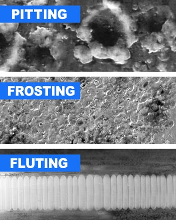
| Pitting | Tiny melted craters of a few microns | Single EDM discharges |
| Frosting | Dull, grey, matte band on the race | Millions of overlapping pits |
| Fluting | Washboard ridges across the race | Pits plus mechanical resonance of the balls |
Frosting is the first visible sign of bearing currents, and the race looks as if it was sand blasted. As the discharges continue, the balls start to bounce on the rough surface at a regular pitch, and the damage organises itself into evenly spaced flutes.
When a failed bearing is removed, cut the outer race and inspect it under good light before throwing it away. A frosted band or regular flutes points to bearing currents and not to poor lubrication.
Detecting Electrical Bearing Damage in 5 Steps
A vibration sensor on the bearing housing picks up fluting as peaks at the outer race defect frequency and its harmonics. Adding these checks to your predictive maintenance route catches damage from bearing currents long before a seizure.
Fluting spacing is set by the ball pass rhythm and the natural frequency of the bearing assembly, which is why flutes look so regular. A single discharge crater is often smaller than the width of a human hair.
7 Proven Fixes for Bearing Currents
AEGIS recommends that motors above about 100 HP use an insulated bearing on one end and a shaft grounding ring on the other end. Industrial Equipment News adds that a grounding ring usually costs less than 1 percent of the total drive and motor system.
Against bearing currents, cable choice matters as much as bearing choice, and the construction of a good drive cable is covered in shielded cable and twisted pair. Terminate the shield with 360 degree glands at both the drive and the motor, not with a long pigtail.
A dv/dt filter mainly protects the winding insulation from voltage spikes, and it only partly reduces bearing currents. A full sine filter with a common mode stage removes most of the common mode voltage, but it adds cost, losses and voltage drop.
Lowering the carrier frequency in the VFD parameter settings reduces the number of discharges per second. It cannot remove the common mode voltage itself, so treat it as a helpful adjustment and not a cure.
Never insulate both bearings without also fitting a grounding ring, because the rotor voltage then finds a path through the coupling into the gearbox or pump bearings. Always give the shaft one intended path to earth.
Choosing a Solution by Motor Size
| Motor size | Main current type | Recommended protection |
|---|---|---|
| Below 55 kW | Capacitive EDM discharge | Shaft grounding ring, shielded cable |
| 55 kW to 100 kW | EDM, some circulating | Grounding ring, HF bonding, consider hybrid bearings |
| Above 100 kW | Circulating HF current | Insulated NDE bearing plus grounding ring on DE |
| Any size, poor bonding | Rotor ground current | HF bonding straps, symmetrical cable, common mode choke |
Myths About Motor Bearing Currents
- Bearing life returns close to its mechanical design value.
- Lower noise and vibration, especially on fans.
- Fewer unplanned outages and less secondary damage.
- Grounding rings are cheap and easy to retrofit.
- No single fix covers every current path.
- Insulated and hybrid bearings cost more and need lead time.
- Filters add losses, heat and panel space.
- Brushes and rings need periodic inspection.
Bearing currents often appear together with electrical stress on the winding, so review the motor insulation class when you plan mitigation. The site earthing design in earthing for process plants also affects how well HF bonding works.
Commissioning Checklist for Drive Fed Motors
- Use symmetrical shielded motor cable with 360 degree shield glands at both ends.
- Fit HF bonding straps between the motor frame, base plate and driven machine.
- Install a shaft grounding ring on motors where EDM is expected.
- Specify an insulated NDE bearing on large frames.
- Measure shaft voltage at commissioning and record the peak value.
- Record baseline vibration spectra for future comparison.
Record these results in the motor history file, together with any power quality issues seen on the same bus. Comparing later readings with this baseline makes early bearing currents easy to spot.
Clarage Engineering Note on Shaft Currents (PDF)
Video: Shaft Current Protection for VFD Motors
Bearing Currents FAQ
They are caused by the common mode voltage produced by the fast switching of the inverter. This voltage couples to the rotor through the stray capacitance of the winding.
The rotor charges up relative to the grounded frame until the grease film breaks down. The resulting discharge current passes through the balls and races and slowly damages them.
Fluting is a pattern of evenly spaced ridges across the bearing race, like a washboard. It develops after frosting, when the balls start bouncing over the rough surface in a regular rhythm.
A fluted bearing makes a clear whine or growl that often changes with speed. Once fluting appears the bearing must be replaced, because the damage keeps growing.
A conductive brush probe touches the rotating shaft and connects to an oscilloscope referenced to the motor frame. The scope should have a bandwidth of at least 100 MHz to show the fast spikes.
Sharp spikes that suddenly collapse show active discharges through the bearing. Industrial Equipment News notes that peaks of 70 V or more are easily seen on some motors.
Yes, a ring with conductive microfibres gives the shaft a lower impedance path than the bearing. The current then flows through the fibres to the frame and the bearing is protected.
It works best against capacitive discharge bearing currents in small and medium motors. On large frames it should be combined with an insulated bearing on the opposite end.
Insulated bearings are usually specified for large motors, typically above about 100 kW or 100 HP. In these machines the circulating high frequency current is the main problem.
Only one bearing, usually the non drive end, is insulated to break the loop. The drive end then gets a grounding ring so the rotor voltage has a safe path.
Lowering the carrier frequency reduces the number of discharges each second, so damage builds up more slowly. It also slightly reduces the high frequency leakage current.
However, it cannot remove the common mode voltage, which is fundamental to a 2 level inverter. Use it together with hardware fixes, such as grounding rings, rather than instead of them.
No, small and medium motors are often the most affected, mainly by capacitive discharge currents. Their bearings are small and the voltage stress on the thin grease film is high.
Clarage notes that most affected bearings fail within 3 to 12 months of operation. A simple grounding ring and good shielded cable prevent most of these failures.
Related Articles
- VFD Working Principle Explained
- dv/dt Filter for VFD Motor Protection
- Motor Insulation Classes
- Vibration Sensor Working
- Shielded Cable and Twisted Pair
External References
- VFD Induced AC Motor Shaft Current and Bearing Damage, Clarage
- Preventing VFD Induced Electrical Damage to AC Motor Bearings, Industrial Equipment News
- Shaft Voltage, Wikipedia
What We Learn Today
- VFD bearing currents come from the common mode voltage of the inverter, coupled to the rotor through stray capacitances inside the motor.
- Discharges first frost the bearing race and then create washboard fluting, which shows up as noise, vibration and blackened grease.
- Shaft grounding rings, insulated or hybrid bearings, symmetrical shielded cable and HF bonding together give the most reliable and lasting protection for drive fed motors.