
A single strike can carry tens of kiloamperes, so the path it takes to earth must be planned long before the storm arrives.
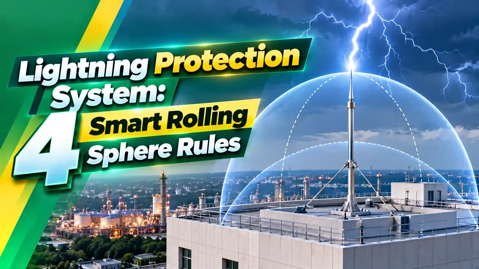
An external lightning protection system intercepts a strike, carries the current safely down the building and spreads it into the soil. The rolling sphere method decides exactly where air terminals are needed.
What Is a Lightning Protection System?
A lightning protection system, often shortened to LPS, is a planned network of air terminals, down conductors and earth electrodes that gives a strike a safe, low impedance path to ground. It works together with surge protection devices that protect the equipment inside the building.
IEC 62305 splits the job into an external part, which intercepts and conducts the strike, and an internal part, which prevents dangerous sparking and surges. This article focuses on the external design.
The three external parts are the air termination, the down conductors and the earth termination. Each must be sized and spaced according to the chosen lightning protection level.
A poor design can be worse than none, because side flashes jump from the conductor into nearby metal or wiring. Correct spacing and bonding prevent this.
How the Rolling Sphere Method Works
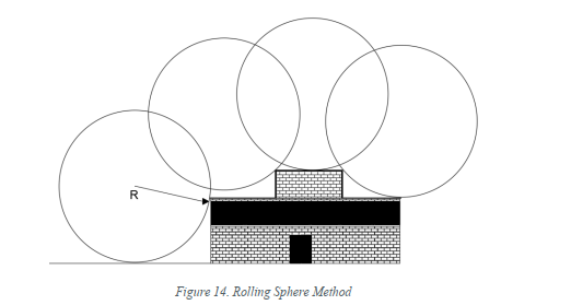
Imagine a giant ball rolled over and around the building in every direction. Any point the sphere touches can receive a direct strike, so it needs an air terminal or conductor.
The sphere radius equals the striking distance of the downward leader for a given minimum current. A smaller sphere reaches into more corners and gives stricter protection.
Axis Electricals notes that Class I uses the smallest sphere and gives the highest protection. The radius grows through Classes II, III and IV.
4 Smart Rolling Sphere Rules by Protection Level
| LPL | Sphere Radius | Mesh Size | Down Conductor Spacing |
|---|---|---|---|
| I | 20 m | 5 m × 5 m | 10 m |
| II | 30 m | 10 m × 10 m | 10 m |
| III | 45 m | 15 m × 15 m | 15 m |
| IV | 60 m | 20 m × 20 m | 20 m |
Hospitals, fuel storage and control rooms usually need LPL I or II. Ordinary buildings often fall into LPL III or IV after the risk assessment.
For hazardous plants, the lightning protection system must also respect hazardous area zones, since a spark inside a zone is itself a hazard.
Protected Zone Formula With Example
Protected radius at height hx = √(h(2R minus h)) minus √(hx(2R minus hx))
h = air terminal height, R = sphere radius, hx = height of the object to protect
Worked example, LPL III:
R = 45 m, rod height h = 10 m, object height hx = 3 m
√(10 × 80) = 28.3 m, √(3 × 87) = 16.2 m
Protected radius ≈ 12.1 m around the rod at 3 m height
The formula applies when the terminal is shorter than the sphere radius. Taller structures also need side protection, because the sphere can touch their walls.
Always cross check with a scaled drawing or 3D software, especially on buildings with several roof levels.
Down Conductors and Earthing
Down conductors split the current so no single path carries the whole strike. They join a ring or rod earth system, designed like any plant earthing system.
IEC 62305 recommends a low earth resistance, commonly around 10 Ω, for the earth termination. Use the earthing resistance calculation guide to size rods and spacing.
Bond all metal parts, pipes and cable trays to the LPS to avoid side flashes. Conductor sizes follow the same logic as the earth conductor size calculation.
Air Terminal Types
Franklin rods placed at touch points and corners.
Overhead wires strung between masts.
Conductors laid in a grid on flat roofs.
Metal roofs and structural steel used as parts of the LPS.
Early streamer emission rods are not recognised by IEC 62305. Designs based only on their claimed radius should be treated with caution.
Rolling Sphere Calculator
Change R to 20 m to see how LPL I shrinks the protected area. More rods or a mesh then become necessary.
- Risk assessment before design.
- Short, straight down conductors.
- Bonding of all nearby metalwork.
- Annual visual inspection and testing.
- Too few down conductors.
- Sharp bends in conductors.
- Unbonded pipes and trays.
- Relying on unproven rod claims.
UL Lightning Protection Guide PDF
Rolling Sphere Design Video
Lightning Protection System FAQ
Related Articles
- Surge Protector Types
- Earthing Resistance Calculation
- Earth Conductor Size Calculation
- TN, TT and IT Earthing Systems
- Earthing in Process Plants
External References
- Lightning Protection Application Guide, UL
- Rolling Sphere Method, Axis Electricals
- Lightning Rod, Wikipedia
What We Learn Today
- The rolling sphere shows every point a strike can reach.
- Sphere radius, mesh size and down conductor spacing depend on the LPL.
- Good earthing and bonding complete the protection.