
When a motor slows faster than its load wants to, the energy has to go somewhere, and the resistor turns it into heat.
A braking resistor lets a VFD stop a high inertia load quickly by burning regenerated energy as heat. Without it, the DC bus voltage rises and the drive trips on overvoltage.
What Is a VFD Braking Resistor?
A braking resistor is a power resistor connected to the DC bus of a VFD through a switching transistor called the brake chopper. It absorbs energy returned by the motor when it acts as a generator during deceleration.
When the drive lowers output frequency faster than the load can slow on its own, the rotor runs faster than the field. The motor then generates power back into the drive.
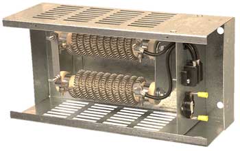
A standard drive has a diode rectifier that cannot send energy back to the mains. The returned energy charges the DC bus capacitors and the voltage rises quickly.
If nothing absorbs it, the drive trips on DC bus overvoltage, one of the common VFD trip causes. The resistor solves this simply and cheaply.
How Dynamic Braking Works
The brake chopper is usually an IGBT controlled by the drive. It switches on above a set DC voltage and off when the voltage falls back.
For a 400 V class drive, the normal DC bus is around 540 to 560 V. The chopper typically switches on well above this level, so always check the threshold in the drive manual.
ABB Technical Guide No. 8 compares this method with regenerative braking, where an active front end returns energy to the supply instead of wasting it.
Braking Resistor Sizing Formulas
Average power = Peak power × Braking time ÷ Cycle time
Worked example:
Chopper voltage Vdc = 700 V
Peak braking power = 15 kW
R max = 700² ÷ 15000 = 32.7 Ω
Choose R between the drive minimum and 32.7 Ω
Braking 10 s every 60 s, duty = 16.7 percent
Average power = 15 × 0.167 ≈ 2.5 kW continuous rating
The resistance must never be lower than the minimum value stated by the drive maker. A lower value draws too much current through the chopper transistor and can destroy it.
Peak braking power comes from the load inertia and the required stopping time. Kinetic energy equals half the inertia multiplied by the square of angular speed.
5 Costly Sizing Mistakes to Avoid
Mistake 4 is a real fire risk. Fit a thermal switch or overload on the resistor and wire it to stop the drive or open the supply.
Configure the drive braking parameters correctly too, as described in VFD parameter configuration. Enable the chopper and set resistor protection values.
Braking Methods Compared
| Method | Energy Use | Cost | Best For |
|---|---|---|---|
| Coast to stop | No braking | None | Fans, low inertia loads |
| DC injection | Heat in motor | Low | Holding at standstill |
| Dynamic braking resistor | Heat in resistor | Low to medium | Occasional fast stops |
| Regenerative front end | Returned to supply | High | Frequent braking, lifts, cranes |
| Common DC bus | Shared between drives | Medium | Multi drive lines |
For frequent heavy braking, regenerative drives often pay back through energy savings. For occasional stops, a braking resistor is the simplest answer.
DC injection braking heats the motor itself, so it should be used only for short periods at low speed.
Where Dynamic Braking Is Needed
Overhauling loads like hoists and downhill conveyors regenerate while running, not only while stopping. Their resistors need much higher continuous ratings.
Motor slip turns negative during regeneration, a concept covered in induction motor slip.
Dynamic Braking Sizing Calculator
Always check that the chosen value is above the drive minimum resistance. Then pick a standard resistor with power rating above the average power.
- Simple and low cost.
- Fast stopping of high inertia loads.
- Prevents DC bus overvoltage trips.
- Works with standard drives.
- Wastes energy as heat.
- Needs space and ventilation.
- Fire risk without thermal protection.
- Not ideal for continuous regeneration.
ABB Electrical Braking Guide PDF
Braking Resistor Wiring Video
Braking Resistor FAQ
Related Articles
- VFD Working Principle
- VFD Overload Trip Causes
- VFD Parameter Configuration
- IGBT Working Principle
- How AC Induction Motor Works
External References
- Technical Guide No. 8 Electrical Braking, ABB
- Resistor Guide on Dynamic Braking, EEPower
- Dynamic Braking in VFDs, Ondrive
- Dynamic Braking, Wikipedia
What We Learn Today
- Regenerated energy raises the DC bus, and the chopper sends it to the resistor.
- Resistance must stay above the drive minimum and power must suit the duty cycle.
- Thermal protection and good mounting prevent overheating and fire.