
Switching a signal fully on and off very fast lets a digital pin control brightness, speed and power almost like an analog output.
Pulse width modulation controls power by switching a signal on and off at a fixed frequency and changing how long it stays on. The average of that fast switching behaves like a variable voltage.

What Is Pulse Width Modulation?
Pulse width modulation, or PWM, is a technique that varies the on time of a square wave while keeping its frequency constant. The ratio of on time to period, called duty cycle, sets the average power delivered.
Because the switch is either fully on or fully off, very little power is wasted as heat. That is why PWM is the heart of efficient converters such as the buck converter.
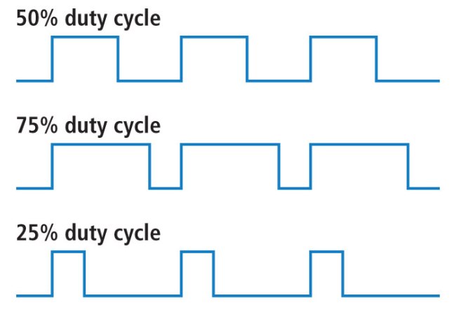
SparkFun describes duty cycle as the percentage of time a digital signal is on over one period. A 50 percent duty cycle means equal on and off time.
The load does not see individual pulses if the frequency is high enough. It responds to the average, which is why a motor runs smoothly and an LED looks steadily dimmed.
Duty Cycle, Frequency and Average Voltage
Frequency and duty cycle are independent. You can have a 25 percent duty cycle at 100 Hz or at 20 kHz, and the average voltage is the same.
The right frequency depends on the load. SparkFun notes that LEDs need at least about 100 Hz to avoid visible flicker, while motors often use 20 kHz or more to stay above hearing range.
Resolution is set by the number of timer bits. An 8 bit PWM has 256 steps, and a 10 bit PWM has 1024, as handled by most microcontrollers.
Pulse Width Modulation Formula With a Worked Example
Average voltage = D × Peak voltage
Frequency f = 1 ÷ Period
Worked example:
Peak voltage = 12 V, f = 1 kHz, so Period = 1 ms
On time = 0.25 ms
D = 0.25 ÷ 1 × 100 = 25 percent
Average = 0.25 × 12 = 3 V
8 bit register value = 0.25 × 255 ≈ 64
The average voltage formula holds for resistive loads and for loads that filter the pulses, such as motors and LC filters. For power in a resistor, remember that power follows the RMS value instead.
For RMS details see RMS value explained. For a PWM square wave, the RMS voltage equals the peak multiplied by the square root of the duty cycle.
5 Uses That Give Instant Control
For servos, SparkFun explains that a 50 Hz signal with a 1.5 ms pulse centres the shaft at 90 degrees. Pulses of 1 ms and 2 ms move it to the ends of travel.
Use 5 relies on a low pass filter, explained in RC low pass and high pass filters. It is a cheap substitute for a DAC when speed is not critical.
Types of PWM Generation
Counter resets each period and output switches once.
Counter counts up and down for symmetric pulses.
Duty cycle follows a sine wave reference.
Optimized switching pattern for three phase inverters.
Sine and space vector methods are used in every VFD. They create an AC motor voltage from a DC bus by modulating power transistors.
Center aligned PWM reduces harmonic content and is preferred for motor control. Edge aligned PWM is fine for lighting and simple tasks.
Switching Devices for PWM
| Device | Typical Frequency | Best Use |
|---|---|---|
| Logic MOSFET | Up to hundreds of kHz | LEDs and small motors |
| Power MOSFET | Tens to hundreds of kHz | Converters and DC motors |
| IGBT | A few kHz to about 20 kHz | High power motor drives |
| Solid state relay | Very low, zero cross types | Heaters with slow cycles |
MOSFETs need a proper gate drive to switch fast, as described in MOSFET gate driver ICs. Slow switching wastes power in every transition.
High power drives use the IGBT because it handles high voltage and current at moderate frequencies.
Where PWM Is Used
Brushless motors are driven by PWM through three phase bridges, as covered in brushless DC motor basics.
Heater control often uses very slow PWM with a period of seconds. This is called time proportional control and works well with solid state relays.
PWM Calculator
Increase the resolution to 10 bits and the same duty cycle needs a register value of about 256. Higher resolution gives finer control.
- Very high efficiency.
- Simple digital control.
- Works with LEDs, motors and converters.
- Fine resolution with modern timers.
- Switching creates EMI.
- Audible noise at low frequency.
- Needs filtering for true analog output.
- Fast edges stress insulation in motors.
Microchip PWM Tips and Tricks PDF
PWM Duty Cycle and Frequency Video
Pulse Width Modulation FAQ
Related Articles
- Buck Converter Working Principle
- VFD Working Principle
- MOSFET Working Principle
- Servo Motor vs Stepper Motor
- LED Working Principle
External References
- PWM Tutorial, SparkFun
- PWM Tips and Tricks, Microchip
- Analog PWM Application Report, Texas Instruments
- PWM, Wikipedia
What We Learn Today
- Duty cycle is on time divided by period, and it sets the average voltage.
- Frequency is chosen to suit the load, from 100 Hz for LEDs to 20 kHz for motors.
- PWM drives LEDs, motors, servos, converters and inverters efficiently.