
A TVS Diode protects sensitive circuits from short, damaging voltage spikes by clamping the excess energy before it reaches downstream components.
A TVS Diode reacts within nanoseconds to a voltage surge, briefly conducting a large current to hold the line voltage near a safe clamping level until the transient energy has passed.
This device is often paired conceptually with a varistor in surge protection design, though the two respond at very different speeds and current levels.
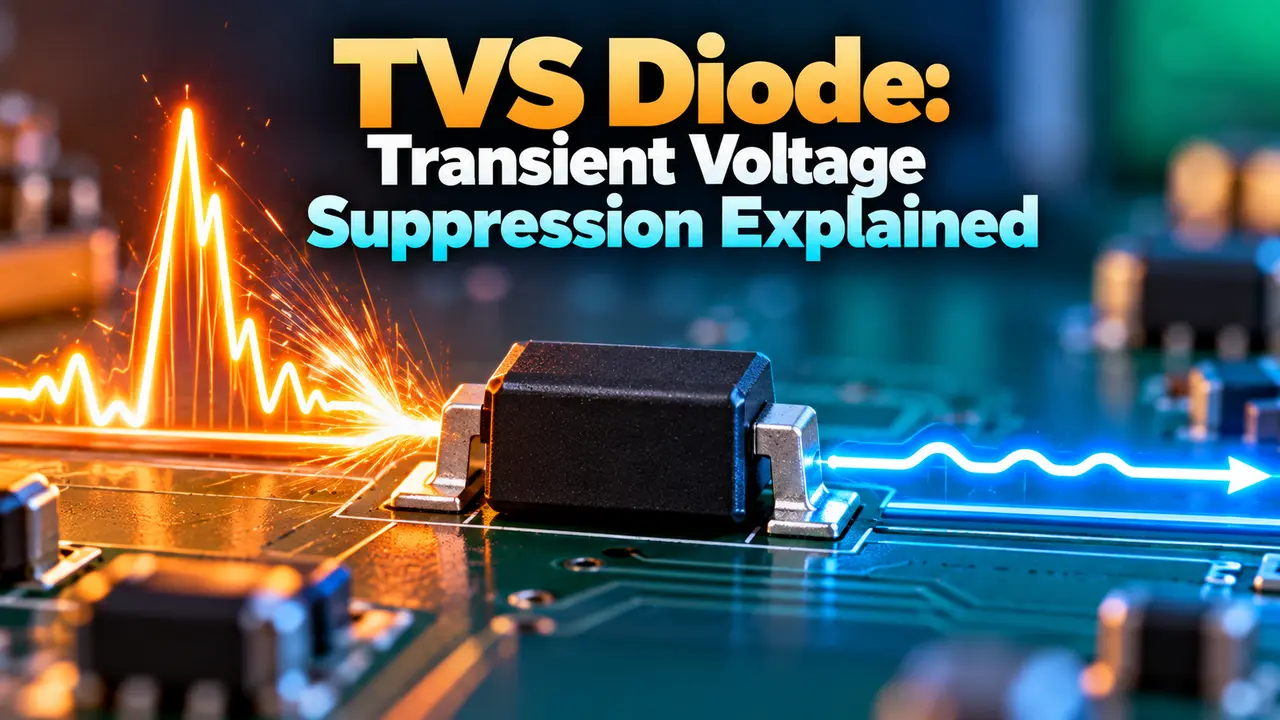
TVS Diode Working Principle
A TVS diode sits idle under normal operating voltage, drawing almost no current and having no effect on the circuit it protects.
The moment a transient, such as a lightning induced surge or an electrostatic discharge event, pushes the voltage above the device's breakdown level, the diode switches into avalanche conduction almost instantly.
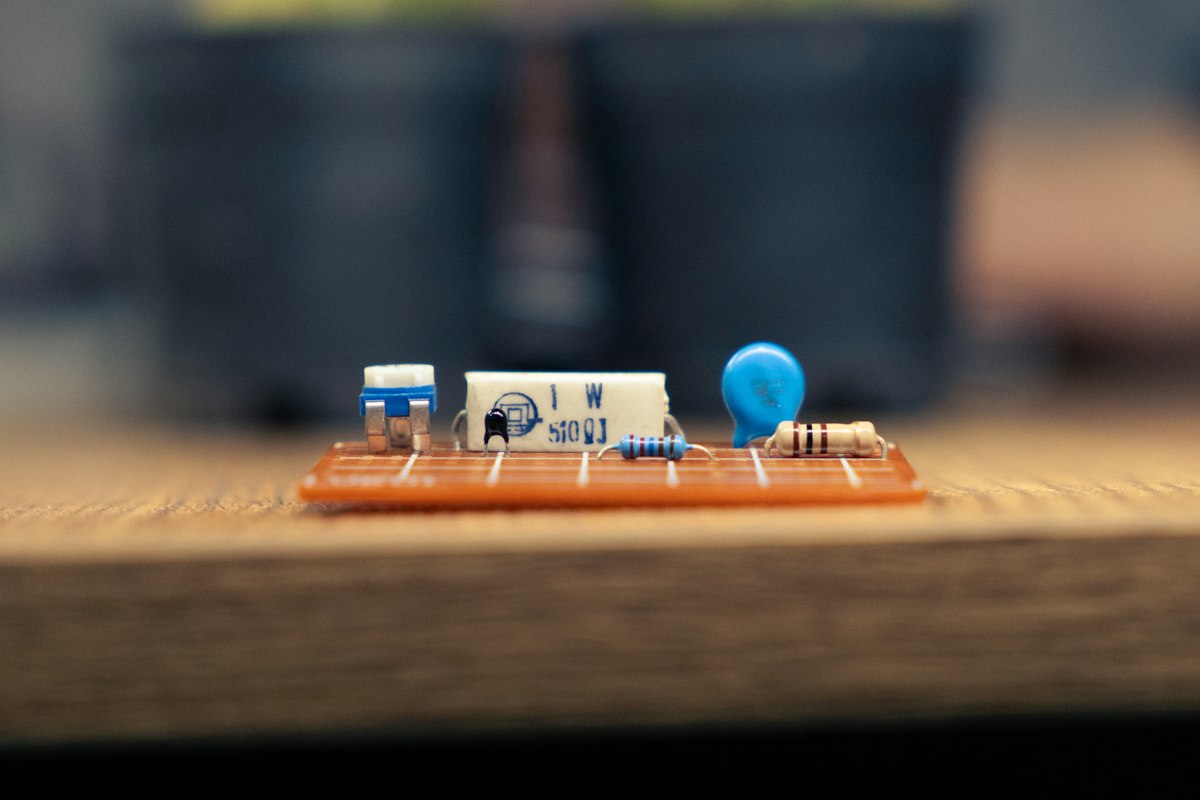
In that avalanche state it behaves much like a low value resistor, diverting the surge current away from the protected circuit and holding the voltage near a defined clamping level.
Once the transient energy has been absorbed and the voltage drops back below the breakdown point, the device returns to its idle, non conducting state on its own, ready for the next event.
Datasheets describe this behavior with a peak pulse power curve, usually plotted for a standard eight by twenty microsecond waveform, which tells a designer how much energy the part can absorb without permanent damage.
That curve is not a fixed number. Repeated pulses in quick succession heat the junction faster than it can cool, so a device rated for a single large pulse may need significant derating if surges arrive close together.
4 Stages of a Clamping Event
Common TVS Diode Types
Protects against surges of one polarity only, commonly used on DC power and signal lines.
Clamps surges of either polarity, suited to AC lines and data lines that swing both directions.
Packs several channels into one package for protecting multi line interfaces such as USB or HDMI.
Designed with reduced junction capacitance so it does not distort fast data signals it protects.
Clamping Response on a Voltage Line
Clamping Ratio Check
Example:
Breakdown voltage = 6.8 V
Clamping voltage = 11.3 V
Clamping ratio = 11.3 divided by 6.8 = 1.66
Selecting a device also means understanding how it compares with a zener diode, since both regulate at a breakdown voltage but this device is built to survive far larger transient currents.
Where TVS Diodes Are Used
Common Selection Mistakes to Avoid
Choosing a device rated only for the nominal supply voltage, without margin for normal ripple or tolerance, is a frequent error that causes nuisance conduction and reduced service life.
A properly sized surge protection device at the service entrance reduces the energy the downstream suppressor must absorb.
Ignoring package inductance is another common oversight. Long leads or a poorly routed PCB trace add inductance that delays the clamping response.
That extra delay can let a fast transient reach sensitive components before the diode fully engages, especially on boards running at higher clock speeds.
Placement on the board matters as much as the part number. A suppressor mounted far from the connector it protects, with a long trace in between, gives an incoming surge extra distance to couple into nearby traces.
Thermal derating is often skipped as well. A device rated for a given peak pulse power at twenty five degrees Celsius will clamp less effectively at higher ambient temperatures.
Designs operating inside hot enclosures, such as outdoor cabinets or engine bay electronics, need a larger safety margin built into the initial power rating selection.
Choosing between the wider family of diode types available for a given interface also shapes cost and board space, since a general purpose rectifier and a dedicated suppressor solve very different problems.
Testing a finished design against a recognized standard, such as an IEC 61000 series ESD immunity test, confirms the protection actually performs as the datasheet promises under realistic surge conditions.
Reviewing the bill of materials for redundant protection is also worthwhile. Some designs stack a suppressor and a series resistor together, which lowers peak current through the diode and extends its usable life considerably.
Clamping Ratio Calculator
Reference Document
Watch: TVS Diodes Explained
TVS Diode FAQs
Related Articles
- What Is a Zener Diode?
- What Is a Varistor?
- Surge Protection Device Selection
- Diode Types Explained
- MOSFET Working Principle
External References
What We Learn Today
- This device idles silently until a transient pushes voltage above its breakdown level, then clamps almost instantly.
- Standoff voltage, clamping ratio, and package inductance all decide how well a device protects a real circuit.
- Correct placement close to the protected interface matters as much as the datasheet rating itself.