
A Neutral Grounding Resistor limits how much current flows during a ground fault, and picking the wrong value can either let a fault burn undetected or trip healthy feeders every time a small fault occurs.
This resistor connects the neutral point of a transformer or generator to ground through a fixed resistance. Its value decides exactly how much current a ground fault can draw.
This connects directly with the broader topic of Grounding Techniques Explained, since an NGR is really one specific method chosen from that wider family of grounding schemes.
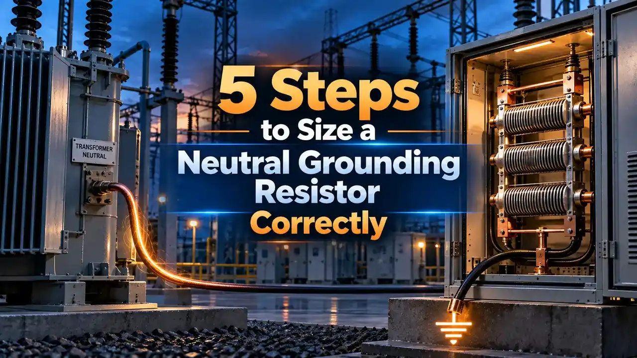
Neutral Grounding Resistor
Most industrial and utility systems do not leave the transformer or generator neutral solidly grounded. Instead a resistor is inserted between the neutral point and ground to control fault current deliberately.
Without that resistor, a single line to ground fault on a solidly grounded system can draw current close to a three phase fault, stressing equipment and creating a serious arc flash hazard.
With the resistor in place, fault current is limited to a known, predictable value, small enough to protect equipment but large enough for protective relays to detect reliably.
The resistor itself sits idle almost all the time, carrying no meaningful current under normal balanced operation, and only springs into action the moment an actual ground fault develops somewhere on the system.
That idle behavior is part of why sizing gets overlooked until a fault actually occurs, at which point an undersized or oversized resistor becomes very obvious very quickly.
Choosing that value correctly is the entire point of this sizing exercise, and it depends heavily on whether the system uses low resistance or high resistance grounding.
5 Steps to Size a Neutral Grounding Resistor
Low Resistance vs High Resistance Grounding
Limits fault current to a range that still trips a protective relay quickly, typically 100 to 1200 amperes on medium voltage systems.
Limits fault current to a few amperes only, letting the plant continue running while the fault is located and cleared.
Neither approach is universally correct. Low resistance grounding favors fast, decisive tripping when a brief shutdown is acceptable, while high resistance grounding favors uptime when the process cannot tolerate a sudden trip.
Many sites end up choosing based on the cost of an unplanned shutdown rather than on electrical theory alone, since a chemical process interrupted mid batch can be far more expensive than the fault itself.
Where the NGR Sits in the Circuit
During normal operation almost no current flows through the resistor. It only carries significant current during an actual ground fault, which is exactly when its sizing matters most.
Calculating the Resistance Value
Example, low resistance grounding:
System voltage = 11000 V, line to neutral = 6350 V
Target fault current = 400 A
Resistance = 6350 divided by 400 = 15.9 ohms
Example, high resistance grounding:
Line to neutral = 6350 V
Target fault current = 5 A
Resistance = 6350 divided by 5 = 1270 ohms
Solid vs Low Resistance vs High Resistance Grounding
| Grounding Type | Typical Fault Current | Arc Flash Risk |
|---|---|---|
| Solid Grounding | Very high, near three phase fault level | Severe |
| Low Resistance | 100 to 1200 amperes | Reduced |
| High Resistance | Typically under 10 amperes | Minimal |
Where NGRs Are Commonly Used
Common Mistakes When Selecting an NGR
Using line to line voltage by mistake: the resistance formula always needs line to neutral voltage, and using the wrong value quietly doubles or triples the calculated resistance.
Other frequent errors include ignoring the resistor's thermal duty cycle rating, and forgetting that a Transformer Vector Group without an accessible neutral point cannot support this kind of resistor at all without an added grounding transformer.
Confusing a ten second short time rating with a continuous duty rating is another costly mix up, since a resistor built for brief fault duty can be destroyed by a fault that persists longer than expected.
Reviewing the resistor's nameplate rating against the plant's actual protection clearing time, not just its calculated ohmic value, is a step worth adding to every commissioning checklist.
NGR Resistance Calculator
Reference Document
Watch: How to Size a Neutral Grounding Resistor
Neutral Grounding Resistor FAQs
Related Articles on This Site
- Grounding Techniques Explained
- Transformer Vector Group Explained
- Protective Relays Explained
- What Is Arc Flash
- Single Line Diagram Symbols and How to Read One
External References
What We Learn Today
- This type of resistor limits ground fault current to a deliberate, predictable value.
- Its resistance value comes from dividing line to neutral voltage by the target fault current.
- High resistance grounding trades fault current for uptime, while low resistance grounding favors fast relay tripping.