
PLC diagnostic and status bits are internal flags set automatically by instructions and the processor. Reading them in ladder logic allows fault detection, instruction state monitoring, and alarm triggering without extra hardware.
We will cover the status bits generated by timer, counter, and math instructions, and what each bit tells you about the instruction state.
We will also learn how the processor's own system status bits work, how to read them in ladder rungs, and how to build practical fault detection routines that use these bits to generate alarms and protect equipment.
Status bits are among the most underused tools in PLC programming. Every timer, counter, and math instruction generates them automatically. Using them reduces fault detection logic and makes programs easier to maintain.
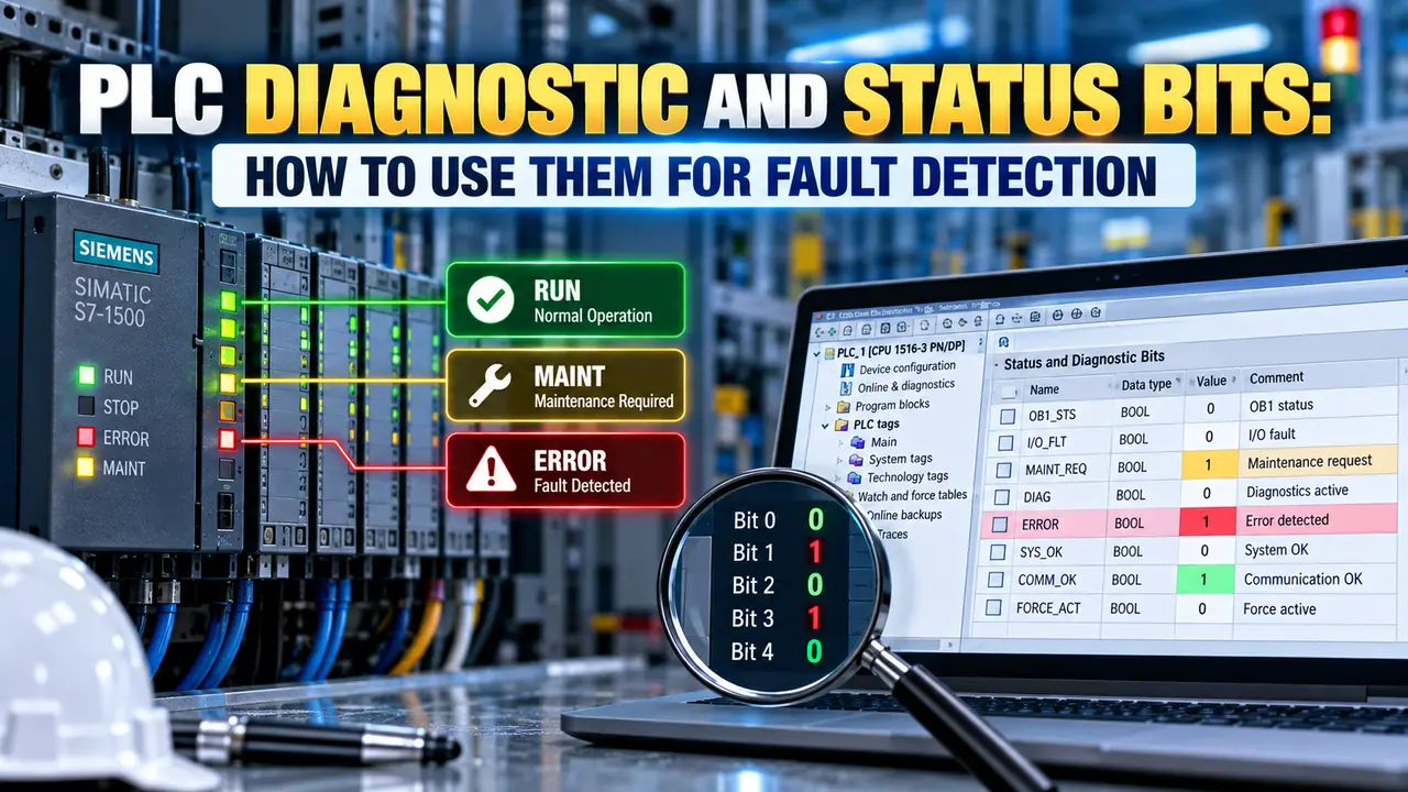
PLC Diagnostic and Status Bits: The Four Main Groups
Set by timer, counter, and move instructions. Examples: EN (enable), DN (done), TT (timer timing), CU (count up), CD (count down), OV (overflow), UN (underflow). Read directly as contacts in ladder rungs.
Set by the processor after any math instruction executes. Examples: Z (zero result), S (negative result), V (overflow), C (carry). Stored in the processor status word and read via status bit contacts.
Set by the I/O chassis when a module has a fault, is missing, or has a blown fuse. Stored in the I/O fault table. Used to detect module failures without direct polling.
Set by the processor itself. Examples: first scan bit (S2:1/15 in RSLogix 500), fault bits, run mode bit, math overflow enable bit. Used for startup initialisation, watchdog monitoring, and major fault detection.
Timer Status Bits: EN, DN, TT
Every TON, TOF, and RTO timer instruction generates three status bits. These bits change automatically as the timer runs and are the primary way to use a timer result in other rungs.
| Bit | Name | When it is ON | Common use in fault detection |
|---|---|---|---|
| EN | Enable bit | The rung enabling the timer is true (timer is enabled) | Confirm the timer rung condition is still present. Use XIC (EN) to seal in a fault latch when a timer starts. |
| TT | Timer timing bit | The timer is actively counting (ACC is incrementing and has not yet reached PRE) | Use XIC (TT) to trigger a warning before the DN bit fires. Signals that an operation is still in progress. |
| DN | Done bit | ACC has reached PRE. The timer has timed out. | The most used status bit. Use XIC (DN) to detect that a sequence step has not completed within the allowed time, triggering a fault alarm. |
The TON timer starts only when the motor output is ON but feedback is not yet received. If the motor starts normally, the feedback closes and the timer rung goes false.
If DN fires, the OTL latches the fault bit.
Counter Status Bits: CU, CD, DN, OV, UN
CTU and CTD counter instructions generate up to five status bits. These allow ladder logic to detect count events, detect overflow, and know when a preset has been reached.
| Bit | Name | When it is ON | Fault detection use |
|---|---|---|---|
| CU | Count up enable | The CTU rung is true (count up input is enabled) | Confirm the count up pulse is arriving as expected. |
| CD | Count down enable | The CTD rung is true (count down input is enabled) | Confirm the count down pulse is arriving as expected. |
| DN | Done bit | ACC has reached PRE | Trigger an alarm or stop a process when the target count is reached. |
| OV | Overflow | ACC has counted above the maximum positive value (32767 for INT) | Detect a runaway counter a counter that keeps incrementing past preset due to a logic error or missing reset. |
| UN | Underflow | ACC has counted below the minimum value (minus 32768 for INT) | Detect a runaway CTD counter decrementing past zero due to a missing stop condition. |
Math Status Bits and I/O Fault Bits
Math instructions set status bits in the processor status word after every execution. The overflow bit (V) signals that a result exceeded the data type range and the stored value is incorrect.
System Status Bits for Startup and Watchdog Use
The PLC processor maintains a status file containing bits that reflect the processor's own operating state. These are read-only bits set by the firmware, not by ladder logic.
For every output that has a required response time (motor starts, valve moves, cylinder extends), add a TON timer with a preset equal to the maximum allowed response time. Wire the timer DN bit to an OTL coil that latches a named fault tag. This pattern uses only three rungs per supervised action, requires no additional field wiring, and gives the HMI operator a named fault rather than a generic PLC fault code.
Watch: PLC Status Bits in Ladder Logic Explained
PLC Status Bits Questions Engineers Ask
Related Articles on This Site
- PLC Watchdog Timer Explained
- PLC Timer Instructions: TON, TOF and RTO
- PLC Counter Instructions: CTU and CTD
- PLC Memory Addressing Explained
- How PLC Scan Cycle Works
External References
- Ladder Logic Fault Detection and Messages | Control Engineering
- Logix5000 General Instructions Reference Manual | Rockwell Automation
What We Learn Today
- PLC diagnostic and status bits are automatic flags set by instructions and the processor. Timer bits EN, TT, and DN indicate whether a timer is enabled, timing, or done. Counter bits CU, CD, DN, OV, and UN indicate counting state, preset reached, overflow, and underflow. Reading these bits in ladder rungs is the simplest way to build fault detection without extra hardware.
- Math status bits S:V, S:Z, and S:N are set by the processor after each math instruction. They detect overflow, zero results, and negative results. Always read math status bits in the rung immediately after the instruction that sets them, as the next math instruction will overwrite them.
- The processor system status file contains bits for first scan, major fault, minor faults, run mode, and watchdog overflow. Use the first scan bit to run startup initialisation logic once. Use the major fault bit in a fault routine to capture and log the fault code before the processor halts.