
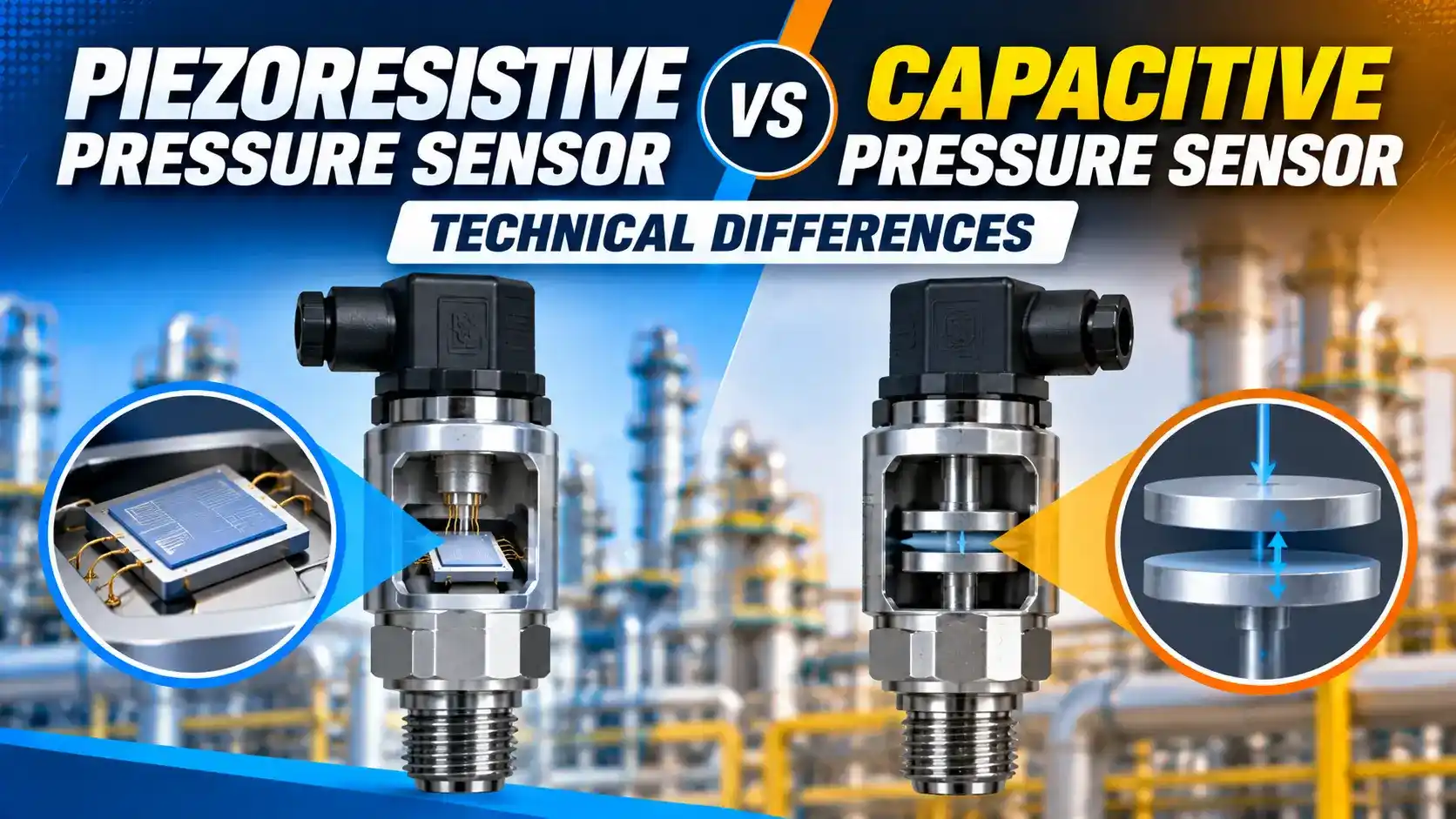
The piezoresistive pressure sensor and the capacitive pressure sensor are the two dominant MEMS-based sensing technologies in industrial transmitters and precision instruments.
Both use a thin silicon diaphragm, but measure deflection by completely different physical principles.
This guide covers the working principle of each piezoresistive pressure sensor type, the key technical differences, temperature characteristics, and how to select the correct technology for your application.
A piezoresistive pressure sensor converts diaphragm strain into a resistance change, measured by a Wheatstone bridge.
A capacitive sensor converts deflection into a capacitance change between two plates.
Piezoresistive sensors offer simpler conditioning and better dynamic response.
Capacitive sensors have lower temperature sensitivity and better resolution at very low pressures.
Piezoresistive Pressure Sensor: Working Principle
Understanding the physics of both types helps you read transmitter specifications correctly.
It also helps you choose the right sensing technology for a demanding application.
The piezoresistive pressure sensor exploits the piezoresistive effect: mechanical stress on a silicon crystal changes its resistivity proportionally.
This change is 50 to 100 times larger in silicon than in metals, making silicon the dominant material for this sensor type.
Four piezoresistors are diffused into a thin silicon diaphragm at the points of maximum stress.
They form a Wheatstone bridge: when pressure deflects the diaphragm, two resistors increase and two decrease, producing an output voltage proportional to pressure.
See the Wheatstone bridge guide for the circuit fundamentals.
V_exc: excitation voltage applied to the bridge (V)
GF: gauge factor of the piezoresistors (silicon: 100 to 175, metal foil: 2 to 4)
ε: mechanical strain at the piezoresistor location (dimensionless)
ΔR/R: fractional resistance change
Typical full-scale output: 10 to 100 mV at 10 V excitation for an industrial pressure range.
This bridge output is amplified, temperature-compensated, and linearised by the ASIC before producing the 4-20 mA or digital output.
In metals, resistance changes mainly from geometric deformation. In silicon, the dominant mechanism is a quantum change in the crystal band structure that alters carrier mobility — a far larger effect.
Capacitive Pressure Sensor: Working Principle
A capacitive pressure sensor uses a flexible silicon diaphragm as one plate of a capacitor, separated from a fixed backplate by a gap of 1 to 10 micrometres.
Pressure deflects the diaphragm, reducing the gap and increasing capacitance.
The capacitance change is the measured signal.
ε₀: permittivity of free space = 8.854 × 10⁻¹² F/m
εᵣ: relative permittivity of the dielectric (≈ 1.0 for vacuum or air gap)
A: overlapping plate area (m²)
d: gap between the diaphragm and the backplate (m)
When pressure reduces d by 10%: C increases by approximately 11%.
Typical full-scale capacitance change: 1 to 20 pF from a baseline of 10 to 100 pF.
This small capacitance change requires a high-frequency AC excitation circuit (typically 100 kHz to 5 MHz) and synchronous detection to resolve accurately.
To achieve 0.1% resolution, the ASIC must resolve changes below 0.1 pF. That requires extremely low-noise switched-capacitor circuits at high clock frequencies — which is why capacitive signal conditioning is more complex and costly than piezoresistive.
If condensate enters the gap of a capacitive sensor (common in vented gauge sensors in humid atmospheres), the dielectric shifts and the reading is permanently offset.
Piezoresistive sensors are less sensitive to this failure because their output depends on resistivity, not permittivity. For humid vented gauge service, choose a piezoresistive sensor with a hermetically sealed reference cavity.
Piezoresistive Pressure Sensor vs Capacitive: Full Technical Comparison
| Parameter | Piezoresistive Pressure Sensor | Capacitive Pressure Sensor |
|---|---|---|
| Physical principle | Stress-induced resistance change in silicon piezoresistors (Wheatstone bridge) | Pressure-induced gap change alters capacitance between diaphragm and backplate |
| Output signal | Low-level voltage (typically 10 to 100 mV FS at 10 V excitation) | Capacitance change (typically 1 to 20 pF FS) |
| Signal conditioning complexity | Low: DC-excited Wheatstone bridge with differential amplifier and temperature correction | High: high-frequency AC excitation circuit, synchronous demodulation, C-to-V conversion |
| Temperature coefficient of offset (TCO) | Higher: silicon piezoresistors show TCO of 0.01 to 0.05% FS per °C without compensation | Lower: capacitance gap geometry has lower temperature dependence than carrier mobility in silicon |
| Temperature coefficient of span (TCS) | Moderate: gauge factor varies with temperature (about 0.02 to 0.1% FS per °C uncompensated) | Lower: the capacitance change per unit pressure is less temperature-dependent |
| Dynamic response / bandwidth | Excellent: DC to several kHz; suitable for dynamic pressure measurement, pressure spikes, and pulsation monitoring | Limited by the AC excitation frequency: typically below 500 Hz for standard capacitive designs |
| Resolution at low pressure | Moderate: limited by Johnson (thermal) noise in the bridge resistors and amplifier noise | High: extremely small gap changes (sub-nanometre) produce detectable capacitance changes, enabling very low full-scale ranges (0 to 1 mbar) |
| Sensitivity to humidity and contamination | Lower: output depends on crystal resistivity, not dielectric constant of surrounding medium | Higher: contamination of the gap changes the dielectric and shifts the reading |
| Overpressure rating | Very high: silicon diaphragm can withstand 10× to 100× rated range before fracture in burst-pressure designs | Moderate: backplate limits the maximum diaphragm deflection (touch-mode designs can survive higher overpressure) |
| Cost | Lower: simpler signal conditioning ASIC, mature high-volume MEMS process | Higher: complex ASIC, tighter manufacturing tolerances for the gap |
| Typical industrial applications | Industrial transmitters (Rosemount 3051, Yokogawa EJX series), process gauges, hydraulic systems, pneumatic controls | Barometric pressure, low differential pressure (HVAC, clean rooms, airflow), precision laboratory instruments |
Temperature Sensitivity in Piezoresistive Pressure Sensor vs Capacitive
Both sensor types require temperature compensation in the signal conditioning ASIC. However, the raw (uncompensated) temperature sensitivity differs significantly, affecting how much correction is needed and what residual errors remain after compensation.
The zero offset also drifts from thermally induced stress in the package.
Uncompensated, total temperature error is 1 to 5% of full scale over 100°C. After ASIC compensation, this reduces to 0.05 to 0.2% URL per 28°C — the figure shown on the transmitter data sheet.
Because the gap and plate area expand together, there is partial self-cancellation. The net uncompensated temperature coefficient is typically 0.01 to 0.05% FS per °C — 3 to 5 times lower than a piezoresistive element.
This is why capacitive sensing dominates in precision barometers, weather stations, and low-range instruments where residual temperature error is critical.
A piezoresistive transmitter needed a larger correction to achieve this figure. Any uncorrected effect (thermal shock, temperature gradient across the body) causes a larger residual error than in a capacitive design.
For critical measurements with rapid temperature changes, ask the manufacturer which technology is used and request the uncompensated temperature coefficient.
Emerson's design uses a 40 mm silicon diaphragm with a hermetically sealed reference cavity, and a capacitance bridge (two capacitors, one on each side) that gives inherent differential temperature cancellation.
This is why the 3051 achieves plus or minus 0.04% of span accuracy. The bridge measures the ratio of two capacitances rather than an absolute value, reducing temperature coefficient significantly.
When to Use a Piezoresistive Pressure Sensor vs Capacitive
Choose Piezoresistive When
Dynamic pressure measurement is needed: spikes, water hammer, pulsation above 10 Hz.
Cost is a primary driver. Typical range: 1 to 1000 bar. See the 4-20 mA signal guide for transmitter output wiring.
Choose Capacitive When
Very low pressure ranges are needed (0 to 1 mbar to 0 to 100 mbar).
The highest temperature stability is required: meteorology, clean rooms, calibration reference. Long-term drift stability over years of service is critical.
Piezoresistive Pressure Sensor Strengths
High bandwidth (DC to kHz). Simple, low-cost signal conditioning. Very high overpressure tolerance. Wide pressure range coverage. Widely available from multiple manufacturers. Proven track record in industrial service since the 1970s.
Capacitive Strengths
Lower temperature coefficient before compensation.
Better resolution at very low pressures and lower noise floor for DC measurements.
Self-cancelling differential capacitance bridge is inherently immune to common-mode temperature shifts.
Sensor Technology Selection Checker
Watch: Pressure Sensor Types Including Piezoresistive and Capacitive
Piezoresistive Pressure Sensor FAQ
External References
- Piezoresistive vs Capacitive Pressure Sensors: Technical Comparison | TE Connectivity (2025)
- Pressure Sensing Technologies and Signal Conditioning | Analog Devices
What We Learn Today
- A piezoresistive pressure sensor uses strain-induced resistance changes in a silicon Wheatstone bridge. Gauge factor in silicon (100 to 175) is 50 times higher than metal foil gauges (2 to 4).
- A capacitive sensor measures the gap change between a flexible diaphragm and a fixed backplate. Full-scale capacitance change is only 1 to 20 pF, requiring complex high-frequency signal conditioning.
- Choose piezoresistive for dynamic measurement (bandwidth to several kHz), high pressure (above 1 bar), and lower cost. Choose capacitive for ultra-low pressure (below 100 mbar) and best temperature stability.