
An inductor stores energy in a magnetic field, not in an electric field like a capacitor.
When current flows through a coil, it builds a magnetic field around each turn. That field stores energy and opposes any change in current, creating the back EMF that makes inductors both useful and dangerous.
This guide covers Faraday's Law, Lenz's Law, the RL time constant, energy storage, inductive reactance, and key industrial applications.
An inductor resists any change in current. Increasing current makes the field expand and the inductor opposes it.
Decreasing current makes the field collapse and the inductor tries to maintain the flow -- releasing its stored energy back, sometimes at a much higher voltage than the supply.
The Physics: Faraday's Law and Lenz's Law
Faraday's Law states that a changing magnetic flux induces a voltage (EMF) in a conductor. In an inductor, the changing magnetic field from changing current induces a voltage in the same coil that produced it.
Lenz's Law tells us that the induced voltage always opposes the change that caused it.
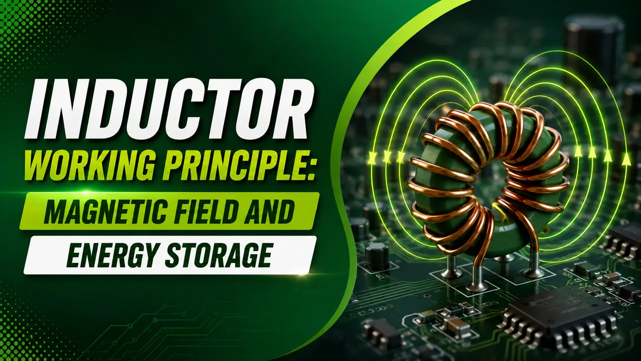
Increase current and the induced EMF opposes the increase. Decrease current and the EMF reverses, trying to sustain it. This opposing voltage is called back EMF.
The result is electrical inertia -- an inductor resists changes in current the same way a flywheel resists changes in rotation speed. The greater the inductance, the more it resists change. See the inductor working principle guide for core types and inductance calculation.
Key Inductor Formulas
L = inductance (henries, H)
dI/dt = rate of change of current (A/s)
Example: 100 mH inductor with current changing at 500 A/s:
V_L = 0.1 × 500 = 50 V back EMF -- even from a 24V supply
L = inductance (H)
I = steady-state current through the inductor (A)
Example: 50 mH at 10 A: E = 0.5 × 0.05 × 100 = 2.5 J
Inductive reactance: XL = 2π × f × L
XL rises with frequency -- opposite to capacitors (XC falls with frequency).
An inductor passes DC freely (XL = 0 at DC) and blocks high frequency AC.
RL Time Constant: Current Rise and Fall
In a series RL circuit, current rises exponentially when voltage is applied, limited by τ = L/R.
The same applies when current falls -- it decays exponentially through the same time constant.
I_max = Vs / R = final steady-state current
τ = L / R (seconds)
Falling current (supply disconnected, current decays through R):
I(t) = I₀ × e−t/τ
I₀ = initial current at the moment of switch-off
At DC steady state: dI/dt = 0, so V_L = 0. The inductor looks like a short circuit to DC.
Inductor Calculator
Inductor vs Capacitor: Key Differences
| Property | Inductor | Capacitor |
|---|---|---|
| Energy storage | Magnetic field (E = ½LI²) | Electric field (E = ½CV²) |
| Resists change in | Current | Voltage |
| DC steady state | Short circuit (V_L = 0) | Open circuit (I = 0) |
| At switch on | Open circuit (opposes current rise) | Short circuit (accepts voltage instantly) |
| Time constant | τ = L/R -- larger R gives faster response | τ = RC -- larger R gives slower response |
| Reactance | XL = 2πfL -- rises with frequency | XC = 1/(2πfC) -- falls with frequency |
| Passes freely | DC and low frequency | AC and high frequency |
| Blocks | High frequency AC (choke) | DC |
| Voltage spike risk | Yes -- sudden current interruption creates high back EMF spike | No -- but charged capacitors store lethal energy at high voltage |
Industrial Applications
Power Supply Chokes and Filters
Inductors in series with a DC supply smooth current ripple. They resist rapid current changes, flattening the output current waveform. Combined with capacitors in an LC filter, they reject switching noise in signal conditioning power rails and in switch mode power supplies.
Transformer Action (Mutual Inductance)
Two coupled inductors share a magnetic core. Changing current in the primary induces a voltage in the secondary through mutual inductance. This is the operating principle of the power transformer and isolation transformers used in instrumentation loops.
Solenoid Valves and Relay Coils
A solenoid coil converts current to magnetic force. See the solenoid valve working principle for the full detail.
Always fit a flyback diode across the coil to suppress back EMF when the coil is switched off.
Power Factor Correction (Reactors)
Inductors (reactors) are fitted in series with capacitor banks in power factor correction panels to detune the bank away from harmonic resonance frequencies. Without a detuning reactor, the capacitors can resonate with supply harmonics and overheat. See the power factor correction guide for reactor sizing.
RF and EMI Filtering
Small inductors (ferrite beads) in series with signal and power lines block high frequency interference. They present low impedance at DC but high impedance at radio frequencies.
See noise reduction techniques for PCB level filter design.
Buck and Boost Converters (DC to DC)
The inductor is the energy storage element in all switch mode DC to DC converters. In a buck converter it smooths pulsed current; in a boost converter it stores energy on the on-time and releases it at higher voltage on the off time.
See PCB design fundamentals for inductor placement guidance.
Watch: Energy Stored in a Magnetic Field and Inductors Explained
Inductor Working Principle Questions
External References
What We Learn Today
- Back EMF = L × dI/dt -- opposes every change in current by Lenz's Law
- Energy stored: E = ½LI² -- in the magnetic field, requires current to be flowing
- RL time constant: τ = L/R -- at 1τ current reaches 63.2% of final value
- XL = 2πfL -- rises with frequency (opposite to capacitor XC which falls)
- At DC steady state: XL = 0, inductor is a short circuit -- only winding resistance remains
- Always fit a flyback diode across any inductive load switched by a transistor or driver IC