
Two cables that look almost identical. Two very different jobs. Mix them up, and the temperature reading drifts in a way that's easy to miss.
Ok, let me explain it properly. One of these cables is made of the same alloy as your thermocouple. The other one only pretends to be, and only within a narrow range.
Thermocouple extension wire vs compensating cable comes down to one core fact: extension wire is made from the same alloy as the thermocouple itself, while compensating cable uses a cheaper, different alloy that only approximates the thermocouple's voltage output within a limited temperature range, and choosing the wrong one introduces a measurement error that has nothing to do with the sensor.
Thermocouple Extension Wire vs Compensating Cable: The Core Difference
Thermocouple extension wire vs compensating cable is a distinction that trips up a lot of students, mostly because both cables are used for the same job, running the signal from a thermocouple to an instrument.
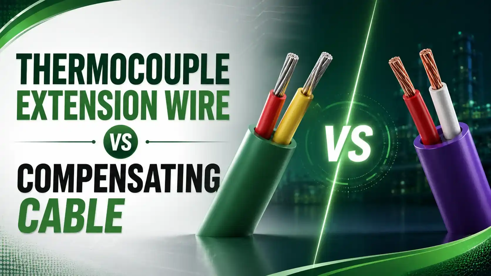
Have you got it so far? Good, because the difference isn't in what they do, it's in how faithfully they do it.
Extension wire is manufactured from the exact same thermoelectric alloy pair as the thermocouple, just in a cheaper, more flexible cable form. It behaves like a direct continuation of the thermocouple itself.
Compensating cable is different. It uses substitute alloys, usually copper and a copper-nickel blend, chosen because their voltage output happens to match the thermocouple's curve closely enough, but only across a limited temperature band, not the sensor's full working range.
Extension Wire vs Compensating Cable, Side by Side
| Characteristic | Extension Wire | Compensating Cable |
|---|---|---|
| Alloy composition | Same alloy pair as the thermocouple itself | Different, cheaper alloy pair that approximates the curve |
| Valid temperature range | Matches the thermocouple across its full working range | Accurate only within a limited ambient band, typically 0-200°C |
| Typically used with | Base metal types, Type J, K, T, E, N | Noble metal types, Type R, S, B (platinum-based) |
| Main reason for use | Practical, flexible cabling at reasonable cost | Avoids running expensive platinum-alloy wire over long distances |
| IEC 60584-3 suffix | Letter "X" appended, for example KX, JX, TX | Letter "C" appended, for example SC, RC, alongside a color code |
Six Practical Differences That Actually Matter in the Field
What "Compensating" Actually Means
The word describes the cable's job, approximating the thermocouple's EMF output using different materials, not literally compensating for anything at the terminal end.
Why Noble Metal Thermocouples Need It
Type R, S, and B thermocouples use platinum and platinum-rhodium alloys. Running that wire for long cable runs would be prohibitively expensive, so compensating cable steps in.
Temperature Range Is Not Optional
Compensating cable is only accurate within its rated ambient range. Route it through a hot area, and the approximation breaks down, introducing real error.
Color Codes Are Type-Specific
Extension and compensating cable colors follow standards like IEC 60584-3 or ANSI MC96.1, and mixing standards or types is a common field mistake.
Polarity Still Matters Equally
Both cable types are polarity-sensitive. Reversing the positive and negative legs produces a badly wrong reading regardless of which cable type is used.
Cost Difference Is Substantial
Compensating cable is typically far cheaper than the equivalent length of genuine platinum-alloy extension wire, which is exactly why it exists as a category at all.
Where the Junction Actually Matters
The point where the thermocouple wire ends and the extension or compensating cable begins is called the transition junction.
This junction needs to sit at a stable, known temperature. If it drifts or sits somewhere with a temperature gradient, the whole calculation the cable relies on starts to break down.
This is a different concept from cold junction compensation, which happens at the instrument's own terminals, not at the cable transition point.
Try It: Wire Mismatch Error Calculator
If the wrong cable, or a mismatched Seebeck coefficient, is used at the transition junction, an error voltage appears. Enter the values below to see how large that error actually is.
Let Us Take an Example
A Type S thermocouple is connected through compensating cable back to a control room instrument.
The transition junction, where the actual thermocouple wire ends and the compensating cable begins, sits inside a warm cabinet at 60°C, while the compensating cable's rated reference is 25°C.
Lab data shows the thermocouple's Seebeck coefficient in this region is 6.0 µV/°C, while the compensating cable's is slightly lower, 5.4 µV/°C.
Stc = 6.0 µV/°C
Swire = 5.4 µV/°C
Tj = 60°C
Tref = 25°C
Step 1: Error voltage
ΔE = (Stc − Swire) × (Tj − Tref)
ΔE = (6.0 − 5.4) × (60 − 25)
ΔE = 0.6 × 35
ΔE = 21.0 µV
Step 2: Temperature error
ΔTerror = ΔE ÷ Stc
ΔTerror = 21.0 ÷ 6.0
ΔTerror = 3.5°C
Have you got it? Good. A 3.5°C error might sound small, but on a process with tight quality limits, that's often enough to matter.
Ok, let me explain the fix. Move the transition junction to a genuinely stable, cooler location, or better, keep it as close as practical to the compensating cable's rated reference range in the first place.
Why Color Codes and Type Letters Matter So Much
Extension and compensating cables are marked with a type letter, K, J, T, E, N, R, S, or B, plus a suffix, X for extension or C for compensating, under IEC 60584-3.
ANSI MC96.1 uses a different but parallel color scheme. Mixing the two systems on the same job is a common, avoidable source of installation error.
According to Inst Tools' explanation of thermocouple extension and compensating cables, checking the cable's printed type marking against the actual thermocouple installed is the single fastest way to catch a mismatch before it causes trouble.
This is also why proper thermocouple installation practice always includes verifying cable type at every termination point, not just at the sensor end.
A Step-by-Step Approach to Getting This Right
Identify the thermocouple type first
Confirm whether the installed sensor is a base metal type or a noble metal type before selecting any cable.
Match the cable letter code exactly
Choose extension wire (X suffix) for base metal types and compensating cable (C suffix) for noble metal types, matching the exact thermocouple letter.
Check the compensating cable's rated range
Confirm the transition junction location will stay within the cable's rated ambient temperature range under all operating conditions.
Verify polarity at every termination
Confirm positive and negative leg polarity at both the sensor end and the instrument end, since a reversed connection causes a large, obvious error.
Keep the transition junction stable
Avoid locating the transition point somewhere with a significant temperature gradient or fluctuation.
Document the cable type and route
Record the cable type, color code standard used, and routing, so future maintenance doesn't have to guess at what's installed.
Good Practices for Extension and Compensating Cable
✓ Do
- Match the cable letter code exactly to the installed thermocouple type
- Keep compensating cable within its rated ambient temperature range at all times
- Verify polarity at every termination point, not just at installation
- Document the color code standard used, since IEC and ANSI systems differ
✗ Don't
- Assume extension wire and compensating cable are interchangeable for any thermocouple type
- Route compensating cable through an area that exceeds its rated ambient range
- Mix IEC and ANSI color code standards on the same installation
- Ignore the transition junction's temperature stability, since it's not just a physical splice
Worth Reading if You Want to Go Deeper
Questions Students and Technicians Often Ask
External References
- Thermocouple Extension and Compensating Cables, Inst Tools
- Difference Between Extension, Compensating & Thermocouple Conductors, Tempsens
What we learn today
- Extension wire is made from the same alloy as the thermocouple, while compensating cable uses a cheaper, different alloy that only approximates the output within a limited temperature range.
- Extension wire is typically used with base metal thermocouples, while compensating cable is typically used with noble metal thermocouples like Type R, S, and B.
- The IEC 60584-3 standard marks extension wire with an X suffix and compensating cable with a C suffix, alongside the thermocouple type letter.
- A worked example showed a mismatched Seebeck coefficient at a 60°C transition junction producing a 21.0 µV error, equal to a 3.5°C temperature error.
- Keeping the transition junction stable and within the compensating cable's rated range, and matching cable type exactly, prevents this class of error entirely.