
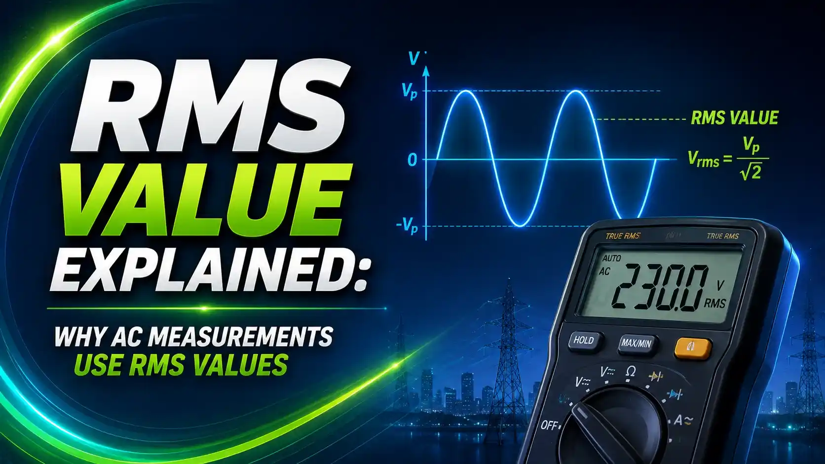
An AC voltmeter reading 230V isn't reporting the peak of the wave, and it isn't averaging it either.
It's reporting the one number that actually predicts how much heat that voltage will produce in a resistor, and that distinction is the entire reason RMS exists.
RMS, or root mean square, is the value of an AC voltage or current that delivers the same heating effect in a resistive load as an equivalent DC value, calculated by squaring the waveform, averaging those squares over one cycle, and taking the square root of that average.
Alternating current is constantly changing, rising to a peak, falling through zero, and reversing polarity many times a second. A plain average of a sine wave over a full cycle is zero, which makes "average" useless as a way to describe how much power an AC source can deliver.
RMS solves this by working through power instead of raw amplitude. Since power dissipated in a resistor is proportional to voltage squared, squaring the waveform first turns every negative half-cycle positive, and the resulting average actually means something physically.
Per All About Circuits' explanation of AC magnitude measurement, RMS is also called the "equivalent" or "DC-equivalent" value for exactly this reason: a 230V RMS AC supply heats a resistive load exactly as much as a steady 230V DC supply would.
This guide breaks down the RMS formula, walks through why it applies specifically to power calculations, and covers where true-RMS versus average-responding meters give different answers on real-world waveforms.
Visualizing RMS on a Sine Wave
The RMS line never touches the peak, and it never touches zero. It settles at a fixed fraction of the peak that depends entirely on the waveform's shape, which for a pure sine wave works out to exactly 1/√2, or about 0.707.
The RMS Formula, Step by Step
RMS = √[ (1/T) ∫ v(t)² dt ] over one full cycle, which in plain terms means: square the waveform, average those squared values over a full cycle, then take the square root.
That 0.707 multiplier only holds for a pure, undistorted sine wave. The moment a waveform gets clipped, chopped by a dimmer, or distorted by a switch-mode power supply, the relationship between peak and RMS changes, which is exactly where true-RMS measurement starts to matter.
Try It: RMS Value Calculator
Enter a peak voltage and waveform type to see the calculated RMS value and the heating-equivalent DC comparison.
A Real Worked Example: 230V Mains
Standard 230V AC mains is a "230V RMS" figure, which means the actual peak voltage on the wire is considerably higher than 230V.
Vpeak = VRMS ÷ 0.707 = 230 ÷ 0.707 = 325 V. The sine wave swings all the way up to roughly +325V and down to -325V, but delivers the same heating power to a resistive load as a steady 230V DC source.
This is also why insulation, capacitor voltage ratings, and switching device ratings in AC circuits must be specified against the peak voltage, not the RMS figure, since the peak is what the insulation actually has to withstand at the top of every cycle.
True RMS vs Average-Responding Meters
True RMS Meter
Computes the actual root-mean-square value of the waveform by sampling and squaring it directly, giving an accurate reading regardless of waveform shape, including distorted or non-sinusoidal signals from VFDs and switch-mode supplies.
Average-Responding Meter
Measures the average of the rectified waveform and multiplies by a fixed 1.1 factor calibrated for pure sine waves. Accurate only on clean sine waves, and increasingly wrong as a waveform distorts.
Per Yokogawa's power meter background tutorial, this difference isn't academic. On a distorted waveform, an average-responding meter can read 10% to 40% off from the true RMS value, which matters directly when sizing conductors, breakers, or verifying compliance against a rated current.
Crest Factor: How Far Peak Sits Above RMS
Crest factor is the ratio of a waveform's peak value to its RMS value, and it's a fast way to judge how "peaky" a signal is.
A high crest factor signal draws short, sharp current pulses instead of a smooth sinusoidal draw, which is common with switch-mode power supplies and rectifier-front-end equipment. Meters and protection devices with a low crest factor rating can be fooled by these narrow, high-amplitude pulses, another reason true-RMS instrumentation matters more with modern electronic loads than it did with older resistive and inductive ones.
Where RMS Actually Gets Used
Do's and Don'ts of Working With RMS
✓ Do
- Use a true-RMS meter on any circuit with variable frequency drives, dimmers, or switch-mode supplies
- Rate insulation and component voltage withstand against peak voltage, not RMS voltage
- Remember that 0.707 only applies to pure, undistorted sine waves
- Use RMS current, not average or peak, when sizing conductors and overcurrent protection
✗ Don't
- Trust an average-responding meter on distorted or non-sinusoidal waveforms
- Confuse a specification's RMS power rating with its peak or "music power" rating
- Assume peak and RMS are the same value for any waveform other than DC
- Ignore crest factor when specifying instrumentation for electronically-loaded circuits
Reference Materials on RMS Measurement
FAQs on RMS Value
External References
What we learn today
- RMS is the AC value that delivers the same heating effect in a resistive load as an equivalent steady DC value.
- For a pure sine wave, RMS equals peak voltage multiplied by 0.707, meaning 230V RMS mains actually peaks at about 325V.
- Average-responding meters are only accurate on clean sine waves; true-RMS meters read correctly on any waveform shape.
- Crest factor measures how far a waveform's peak sits above its RMS value, and electronic loads can exceed 3.0 versus 1.41 for a sine wave.
- Component insulation should be rated against peak voltage, while conductor and breaker sizing should be based on RMS current.