
Every time a car radio locks onto a station without a single moving part, a varactor diode is doing the tuning.
It has no dial, no rotating plates, and nothing mechanical at all. Just a voltage.
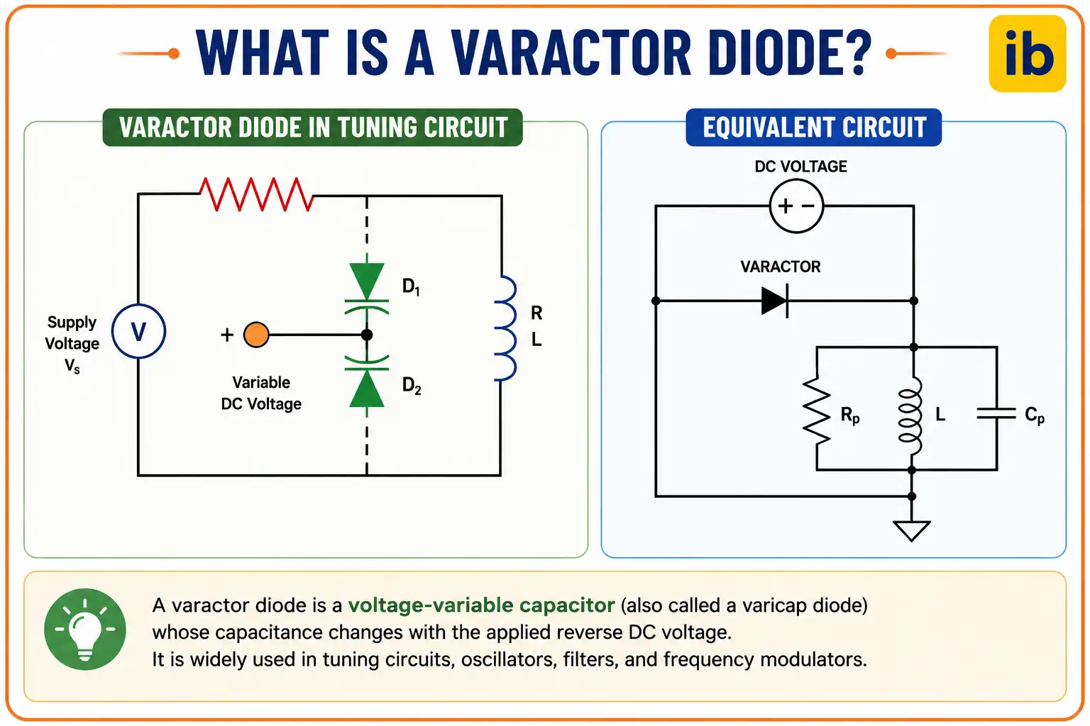
A varactor diode, also called a varicap or tuning diode, is a reverse-biased PN junction diode engineered so its capacitance changes smoothly with applied voltage, letting a circuit be tuned electronically instead of mechanically.
Before varactor diodes existed, tuning anything meant physically moving something. Old radios used an air-gap variable capacitor with metal plates that rotated closer together or further apart as you turned a dial.
That mechanical approach worked, but it had real limits. It couldn't be controlled remotely, it wore out with use, and it was far too slow and bulky for the frequencies modern electronics need to tune.
The varactor diode replaced all of that moving hardware with a single, elegant electrical trick. It takes a perfectly ordinary PN junction diode and puts it to work in a way most diodes are never used.
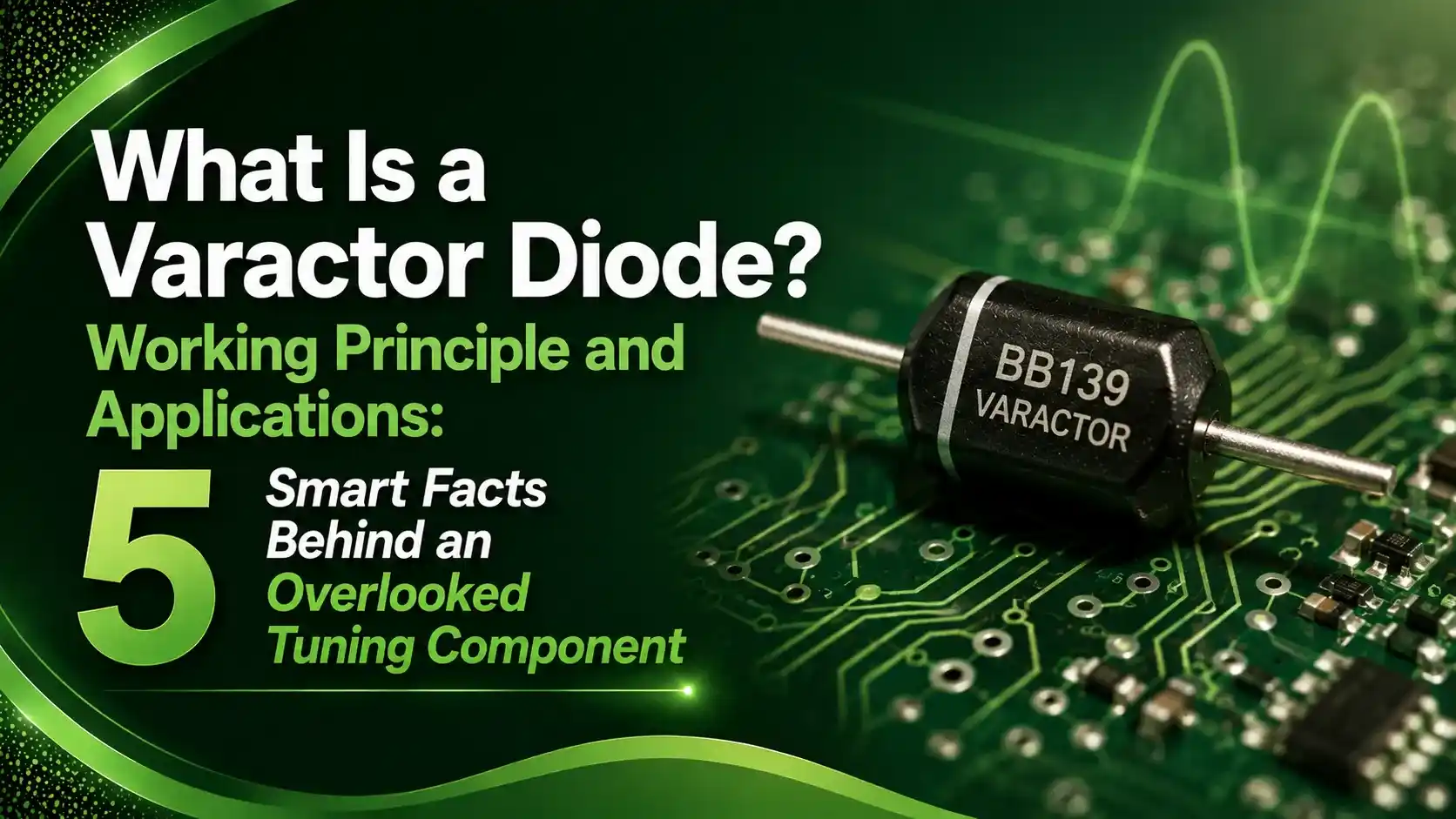
Instead of conducting current, it's operated permanently in reverse bias, right at the point where almost no current flows at all. In that state, the diode isn't acting like a diode anymore. It's acting like a capacitor.
The genuinely clever part is that this capacitance isn't fixed. Changing the reverse voltage physically widens or narrows the diode's internal depletion region, and that directly changes how much capacitance the device presents to the circuit around it.
Once you see the diode this way, an entire category of electronic tuning starts to make sense. This guide covers exactly how that capacitance is controlled, the math behind it, and where these components actually show up.
5 Smart Facts About How a Varactor Diode Works
These five points cover the physics, the formula, and the real limits engineers design around.
Always Operated in Reverse Bias
Unlike a normal diode used to conduct current, a varactor is deliberately kept reverse-biased so it never conducts, only stores charge.
The Depletion Region Is the Dielectric
The P and N regions act as capacitor plates, while the depletion region between them behaves as the insulating dielectric.
Capacitance Follows a Power Law
Capacitance drops as reverse voltage rises, following C = C0 / (1 + V/Vbi) raised to a grading exponent set by the doping profile.
Doping Profile Sets the Tuning Range
Abrupt junctions give predictable, moderate tuning; hyperabrupt junctions are engineered for much wider capacitance ratios.
Quality Factor Limits Usable Frequency
Series resistance in the undepleted silicon caps how high in frequency a varactor stays efficient, defined by its Q factor.
Abrupt vs Hyperabrupt Junction
The doping profile chosen during manufacturing decides how aggressively capacitance responds to voltage.
Abrupt Junction
Constant doping concentration. Grading exponent near 0.47 to 0.5. Predictable, moderate tuning ratio, tight tolerances.
Hyperabrupt Junction
Doping increases with distance from the junction. Grading exponent from roughly 1.5 to 2.5, giving a steeper C-V curve.
Why Reverse Voltage Controls Capacitance
The physical picture behind the formula is simple, even though the math looks dense at first.
A varactor diode is really just an ordinary parallel plate capacitor in disguise, except one of its plates can be pushed further away or pulled closer purely by voltage, with nothing mechanical involved at all.
Interactive Capacitance Formula
This is the real equation manufacturers use to characterize every varactor diode. Pick a junction type, set the voltage, and see the capacitance update live.
Q Factor and Frequency Limits
Real varactor diodes stop performing well above a certain frequency, governed by their quality factor.
| Circuit Type | Frequency Limit Rule |
|---|---|
| Voltage controlled oscillator (VCO) | Usable up to the frequency where Q drops to about 10 |
| Tunable filter | Usable up to the frequency where Q drops to about 100 |
| Q vs frequency relationship | Q = 1 / (2 x pi x f x Rs x C), Q falls as frequency rises |
Where Varactor Diodes Are Used
FM Radio Tuning
Electronic station selection replacing mechanical variable capacitors.
Voltage Controlled Oscillators
Setting resonant frequency in PLLs and frequency synthesizers.
TV Auto-Tuning
Historic and modern channel selection circuits.
Remote Controls
Frequency modulation in simple RF remote transmitters.
Frequency Multipliers
Nonlinear capacitance used to generate harmonic frequencies.
Phase Shifters
RF phase control in beamforming and radar systems.
Do's and Don'ts of Varactor Diode Selection
✓ Do
- Keep the reverse breakdown voltage a safe margin above the maximum tuning voltage
- Match junction type to the tuning ratio the circuit actually needs
- Check Q factor at the actual operating frequency, not just the datasheet reference frequency
- Account for temperature sensitivity, especially with hyperabrupt devices
✗ Don't
- Forward bias a varactor diode, even briefly, since it defeats its purpose entirely
- Assume a wide tuning ratio always means better performance for every application
- Ignore reverse leakage current as a sign of diode quality
- Use a low-Q varactor near its frequency limit in a low-phase-noise oscillator design
Reading a Tuning Ratio Off a Datasheet
Manufacturers report varactor performance as a capacitance ratio between two reverse voltage points, usually a low and a high value in the operating range.
A 4:1 ratio means the capacitance at the low voltage is four times larger than at the high voltage, directly setting how far a tuning circuit's frequency can sweep.
This is the single most important spec for matching a varactor to a given VCO or filter design, more important in practice than the raw zero-bias capacitance value alone.
Reference Materials on Varactor Diodes
FAQs on Varactor Diodes
External References
- Abrupt and Hyperabrupt Varactor Diodes, Electronics Notes
- Using a Varactor Diode in a Tuning Circuit, Cadence PCB Design Blog
- Varactor Diode: Principles, Tuning Circuits, and Frequency Multipliers, RF Wireless World
- Varactor Diodes Application Note, Skyworks Solutions
- Demonstration of a 1GHz Discrete VCO (AN11225), NXP Semiconductors
What we learn today
- A varactor diode is a reverse-biased PN junction whose capacitance changes with applied voltage, replacing mechanical variable capacitors with a purely electrical control.
- The depletion region acts as the capacitor's dielectric, with the P and N regions serving as its two plates.
- Capacitance follows C(V) = C0 / (1 + V/Vbi) raised to a grading exponent gamma, set by the diode's doping profile.
- Abrupt junctions give a moderate, predictable tuning ratio near 2:1 to 4:1, while hyperabrupt junctions can exceed 10:1.
- Q factor limits usable frequency, with VCOs typically usable to where Q drops to about 10, and filters to where Q drops to about 100.