
Since its invention in 1897, the cathode ray oscilloscope has been the instrument engineers reach for whenever a signal needs to be seen, not just measured. This guide covers how it actually works, and includes a live simulated screen you can control yourself.
A cathode ray oscilloscope does not just measure a signal, it draws it, turning voltage over time into a shape you can actually see and interpret at a glance.
A CRO is an electronic test instrument used to visualize electric signals, measure signal characteristics like voltage, time, and frequency, and analyze signal behavior over time. It remains an integral part of modern oscilloscopes used across electrical, medical, industrial, and communication systems.
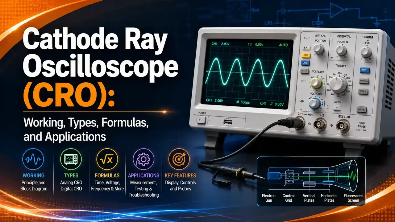
Before going in depth into the cathode ray oscilloscope, it helps to first understand the cathode ray tube, the core technology that makes CRO possible in the first place.
Cathode Ray Tube (CRT): The Core Technology
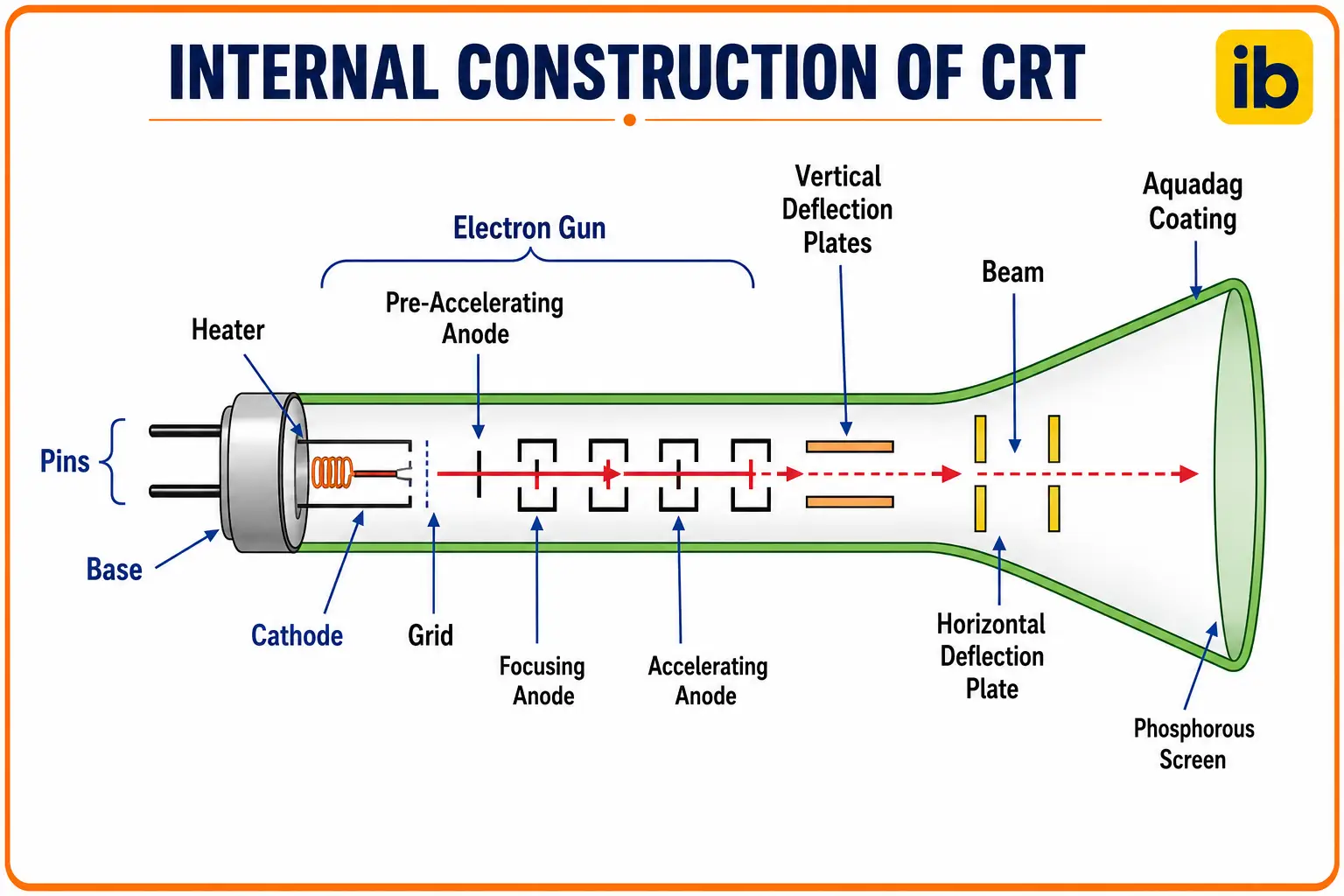
A CRT is a vacuum tube type of display technology that uses electrons to produce images on a screen as visual waveforms. It acts as the main part through which a CRO's functionality is actually carried out.
Construction and Components of a CRT
Heater and Cathode
The heater warms the cathode, which is coated with barium oxide. Once sufficiently heated, the cathode emits a stream of electrons.
Grid
Held at a negative potential and made from nickel, the grid controls the intensity of the electron beam heading toward the anode.
Pre-Accelerating and Focusing Anodes
The pre-accelerating anode gives the beam an initial boost before the focusing anode aligns it into a coherent stream.
Accelerating Anode
Connected to a common positive potential of around 1500 volts along with the pre-accelerating anode, this final anode speeds the aligned beam up again before it reaches the screen.
All of these components together form what is called the electron gun.
Working of a CRT
The electron gun shoots a stream of electrons, sped up and focused into a thin beam by the high voltage anodes described above. This beam is aimed at a screen coated with phosphor, and when the electrons strike it, the phosphor lights up, creating the visible display.
Deflection plates control the beam's position. By applying voltages to these plates, the beam can be pushed up, down, left, or right, reaching any point on the screen. The phosphor's glow lasts just long enough for a moving beam to trace out a smooth, continuous image rather than a series of disconnected dots.
Applications of CRTs
TVs and Monitors
Displayed video and image content for decades before flat panels took over.
Radar Systems
Display radar signals for aircraft, ship navigation, and weather monitoring.
Medical Equipment
Display images such as X-rays to support diagnosis.
Scientific Instruments
Used in spectroscopes, chromatographs, and similar lab equipment.
Oscilloscopes
Analyze waveforms from electrical signals directly.
Cathode Ray Oscilloscope (CRO)
A cathode ray oscilloscope is a device used for measuring and displaying different forms of electrical signals. While a CRT is a type of display technology, in a CRO it functions specifically as the display tube for the whole instrument.
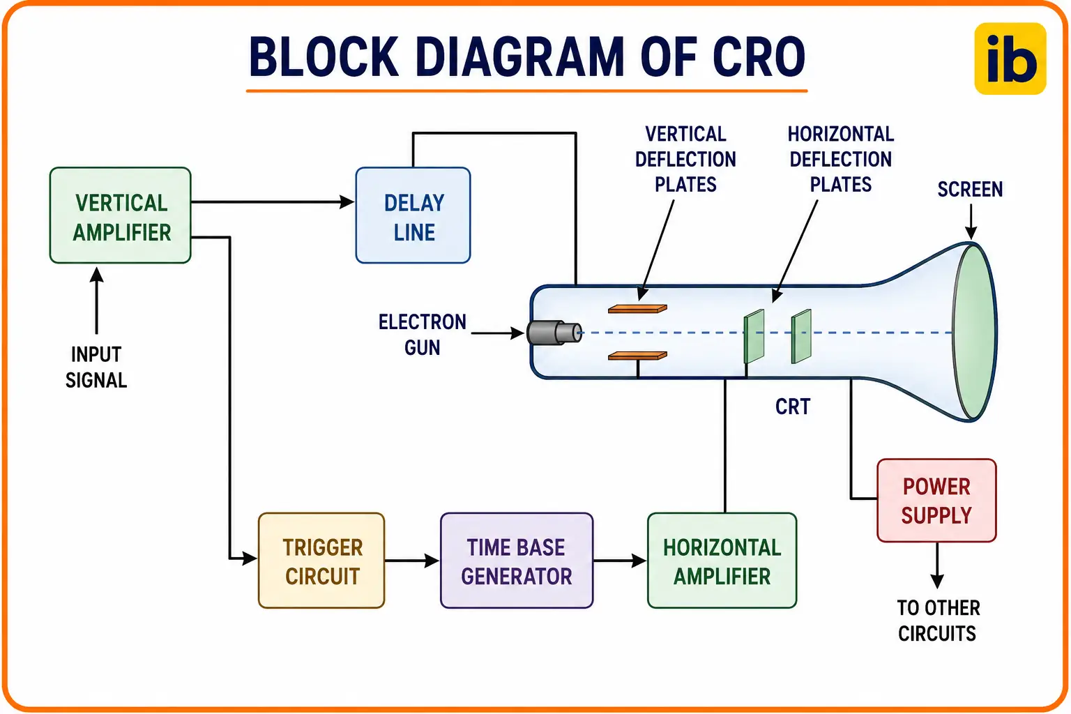
Construction and Components of a CRO
| Component | Function |
|---|---|
| Cathode Ray Tube | Emits and controls electrons to form the signal image on the fluorescent screen |
| Vertical Amplifier | Amplifies the input signal for display on the CRT screen |
| Delay Line | Provides a signal delay applied to the vertical deflection plates |
| Trigger Circuit | Produces a triggering signal to synchronize horizontal and vertical deflection |
| Time Base Generator | Produces a sawtooth signal for horizontal deflection of the beam |
| Horizontal Amplifier | Amplifies the sawtooth signal for the horizontal deflection plates |
| Power Supply | Produces high and low voltages for the CRT and other circuits respectively |
Working of a CRO
The vertical deflection plates move the beam up and down based on the input signal's amplitude, forming the Y axis of the waveform. The horizontal deflection plates shift the beam left and right, forming the X axis, controlled by the time base generator for a steady sweep across the screen.
To keep the waveform stable, the CRO uses a triggering mechanism that syncs the horizontal sweep with a specific point in the signal, producing a consistent trace rather than a jumping image.
Worked example: With 2 vertical divisions at 10 V/division, amplitude equals 20 V. With 3 horizontal divisions at 1 ms/division, the time period equals 3 ms, giving a frequency of 1 ÷ 0.003, or about 333.3 Hz.
🖥️ Interactive Oscilloscope Screen Simulator
Adjust the controls to see a live simulated trace, just like a real CRO screen, with the amplitude, time period, and frequency calculated automatically below.
CRO Modes of Operation
Y-T Mode
The most common mode. The Y axis represents voltage, and the X axis displays time.
X-Y Mode
Displays one signal as a function of another, producing Lissajous patterns commonly used to compare phase and frequency.
Dual-Trace Mode
Displays two signals simultaneously on the same screen for direct comparison.
Sweep Mode
Displays time varying signals as the beam sweeps continuously across the screen.
Types of CRO
| Type | Description |
|---|---|
| Analog CRO | Uses analog circuits to display waveforms directly |
| Digital Storage CRO | Converts analog signals to digital data and analyzes waveforms using digital signal processing |
| Mixed Signal CRO | Combines analog and digital channels simultaneously to analyze both together |
Watch: CRO Block Diagram and Working
This video covers the block diagram of a CRO alongside the underlying CRT structure and working.
Video: "CRO Block Diagram and Working", via YouTube.
Advantages and Disadvantages of CRO
✔ Advantages
- Real time waveform display
- High bandwidth capability
- Multiple signal analysis in one instrument
- Useful across audio and radio frequency analysis
- Genuine triggering capability for stable traces
✘ Disadvantages
- Costly compared to simpler test instruments
- Less portable due to weight
- Limited data storage on analog units
- Difficult to repair internally
- Prone to drift, requiring regular calibration
A CRO does not just tell you a voltage exists, it tells you its shape, and shape is often the fastest way to tell a clean AC signal from a digital one, or a healthy circuit from a failing one.
Applications of CRO
- Determining the amplitude of a waveform
- Comparing the phase and frequency of electrical signals
- Measuring capacitance and inductance values
- Analyzing modulation, demodulation, and transmission, plus measuring SNR and distortion, in communication systems
- Monitoring body parameters like heartbeat rate and nervous system reactions in medical settings
Troubleshooting Common CRO Errors
| Problem | Solution |
|---|---|
| Excessive noise in the waveform | Use proper grounding, adjust time base settings, apply input filters if needed |
| Input signal not triggering | Adjust trigger level and coupling (AC/DC), confirm signal is within trigger threshold, check trigger source and channel |
| Waveform is distorted | Check vertical sensitivity settings, rule out interference from nearby devices, confirm the probe is properly connected |
| Phosphor burn-in | Reduce brightness settings, use screensavers where available, or replace the screen if needed |
FAQs on Cathode Ray Oscilloscopes
You May Also Like
Electrical Units of Measure Explained: Formulas, Prefixes, and Conversion Calculator
Reading a CRO screen accurately depends on being comfortable with volts, time, and frequency units. This guide covers all 10 standard electrical units with their own interactive calculators, a solid companion to interpreting any waveform correctly.
Read Full Article →External References
- Cathode Ray Oscilloscope (CRO), Electronics For You
- Oscilloscope, Wikipedia
- Cathode Ray Tube, Wikipedia
What we learn today
- A cathode ray tube uses an electron gun, deflection plates, and a phosphor screen to turn an electron beam into a visible trace.
- A CRO builds on the CRT with a vertical amplifier, time base generator, and trigger circuit to display a stable, accurate waveform.
- Amplitude, time period, and frequency all follow directly from the vertical and horizontal division readings on the screen.
- Y-T, X-Y, dual-trace, and sweep modes each suit a different kind of signal comparison or analysis.
- Analog, digital storage, and mixed signal CROs each trade off cost, portability, and analysis capability differently.