
Electrical Measurement · Current Sensing · Instrumentation
Shunt Resistors in Instrumentation: 5 Essential Facts Every Engineer Should Know
Measuring hundreds of amps of DC current safely comes down to a deceptively simple trick, a precisely known resistor and a voltmeter. This guide explains shunt resistors in instrumentation in depth, how they work, how they are rated, and how their small millivolt signal reaches a PLC.
Why You Can't Just Wire a Meter Directly Into a High Current Circuit
Measuring current sounds simple in theory, connect a meter in series and read the number. In practice, measuring genuinely high DC current this way is dangerous and impractical. The meter itself would need conductors thick enough to carry hundreds of amps, its internal components would need to survive that current without overheating, and any fault inside the meter would put the full current directly at risk of arcing or fire. A shunt resistor exists specifically to remove that risk.
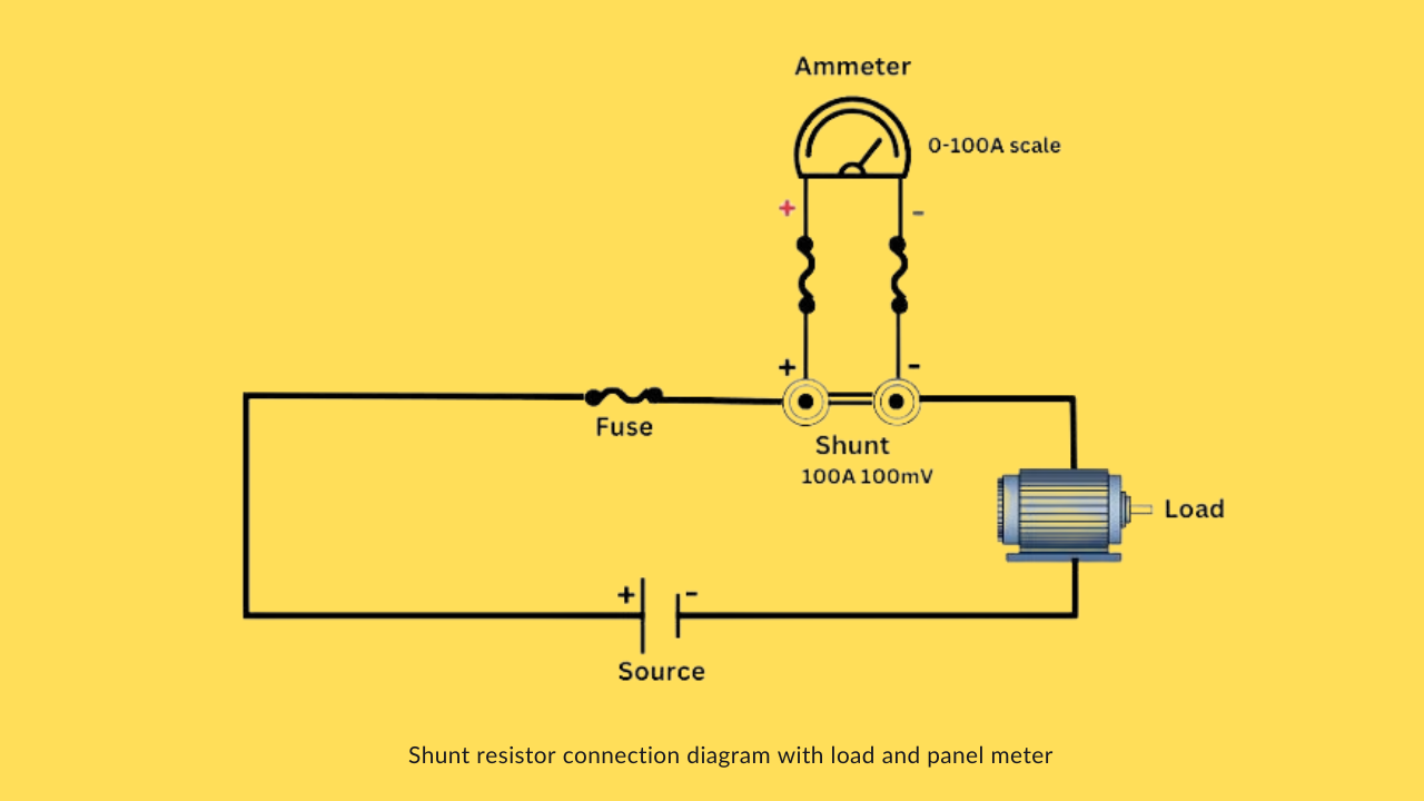
A shunt is a precisely manufactured, very low resistance element wired in series with the load. Rather than forcing the meter to carry the full current itself, the shunt carries that current instead, and the meter only ever has to measure a small, safe voltage across it. For an instrument engineer working on plant data acquisition, this distinction matters immensely: current transformers handle this job on the AC side of a system, while shunt resistors are the equivalent tool for DC circuits, such as rectifier output current or battery charge and discharge current.
5 Essential Facts About Shunt Resistors in Instrumentation
How a Shunt Resistor Actually Measures Current
Physically, a typical shunt resistor consists of two larger terminals made from brass or copper, connected through a low resistance strip, commonly manganin, chosen specifically for its very stable resistance across a range of temperatures. Current entering the circuit flows through this strip on its way to the load. Two smaller terminals sit across that same strip, tapping off a voltage reading that corresponds directly to how much current is passing through.
During manufacturing, each shunt is calibrated so that its resistance is known with real precision. Once installed, measuring the voltage between those two small terminals, commonly labeled A and B, and applying Ohm's Law with the known resistance value, gives an accurate current reading without ever routing that full current through the measuring instrument itself. This is exactly why the typical multimeter, which struggles to measure resistances below roughly one ohm accurately, is not a suitable tool for characterizing a shunt directly, the shunt's entire usefulness depends on a resistance small enough that it barely affects the circuit, yet stable enough to give a trustworthy voltage to current conversion.
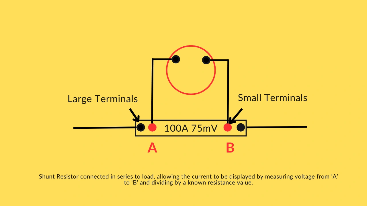
Because the shunt's resistance is so low relative to the rest of the circuit, the voltage it drops is virtually negligible compared to the load's own operating voltage. This matters in practice, since it means the shunt does not meaningfully rob the load of usable voltage even while carrying its full rated current. Any conductor with a sufficiently low and known resistance, in principle even a length of copper wire, could theoretically serve as an improvised shunt, though a properly manufactured, temperature stable shunt is what makes accurate, repeatable readings realistic in an actual instrumentation application.
Understanding the Shunt Rating System
Every shunt carries two numbers, typically engraved on its body or printed on the associated meter face, such as 100 amps and 75 millivolts. The first number is the maximum current the shunt is rated to carry continuously. The second number is the voltage that appears across its sensing terminals specifically when that maximum rated current is flowing. A 50 millivolt shunt design is equally common, where the shunt and its paired meter movement are built so that 50 millivolts corresponds to full scale current on the dial.
This matching matters more than it might first appear. A panel meter calibrated for a 100A, 50mV shunt will read completely incorrectly if it is instead connected to a 100A, 75mV shunt, even though both shunts share the same current rating. The meter's internal scaling assumes a specific millivolt to full scale relationship, and mismatching that relationship produces a confidently displayed, entirely wrong number. Anyone replacing a damaged shunt in the field needs to match both numbers on the nameplate, not just the current rating alone.
Ammeter and Voltmeter Design Share the Same Underlying Principle
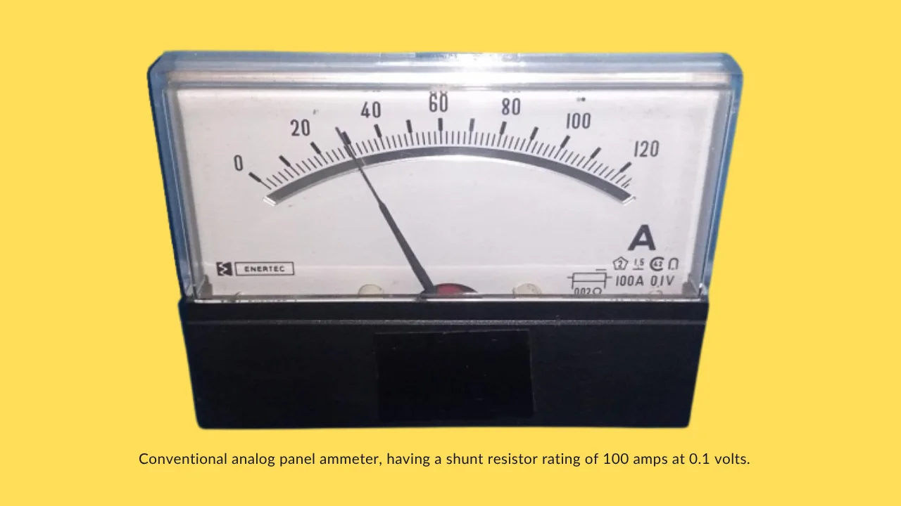
Analog panel ammeters and voltmeters actually rely on the identical basic movement internally, the difference lies entirely in how that movement is wired into the rest of the circuit. In an ammeter, a shunt resistor is placed in parallel with the meter movement, diverting the vast majority of the circuit's current around the sensitive coil while letting only a small, proportional fraction, along with a correspondingly scaled voltage, drive the actual needle deflection. A voltmeter, by contrast, uses a series resistor rather than a shunt, deliberately limiting current into the meter movement so that a specific voltage input produces the expected full scale deflection.
A common design point ties both instruments together elegantly: many classic meter movements are built so that exactly 50 millivolts across the coil produces full scale deflection, regardless of whether that movement is wired as an ammeter reading up to 100 amps or a voltmeter reading up to some rated voltage. For currents up to roughly 50 or 60 amps, the shunt is often small enough to mount directly inside the instrument case. Beyond that, the physical size of the shunt and the heat it generates typically force it to be mounted externally, with heavier cabling connecting it back to the meter movement itself. Switchboard voltmeters follow a similar pattern up to about 300 volts, beyond which an additional series resistor is mounted externally rather than crammed inside the instrument housing.
Converting a Shunt's Output for a PLC or RTU
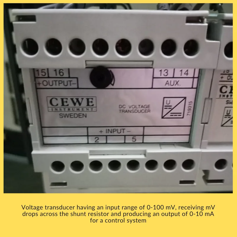
A raw shunt signal, often in the range of 0 to 100 millivolts, is far too small and too fragile to send any meaningful distance to a control room. Before that signal reaches a PLC or RTU analog input card, it typically passes through a dedicated DC voltage transducer, a device built specifically to accept a small millivolt input range and output a standardized, more robust signal such as 0 to 10 milliamps.
That standardized current signal is exactly what a PLC or RTU analog input module is designed to digitize, converting it into a usable value for remote monitoring, trending, and control logic. This same fundamental chain, shunt to transducer to standardized signal to PLC, connects directly to the broader logic behind why standardized current signals dominate industrial instrumentation generally, since they resist noise and voltage drop over long cable runs far better than a raw, unamplified low level signal ever could.
Calculating Current From a Shunt Reading
Or, using the shunt's rated values directly:
Current = (Measured Voltage / Rated Voltage) × Rated Current
Example: A shunt rated 100A at 75mV currently reads 45 mV across its terminals Current = (45 mV / 75 mV) × 100 A = 60 A This ratio method works directly from the nameplate rating without needing to calculate the shunt's actual resistance value separately, which is exactly how most panel meters and transducers are scaled internally.
Shunt Resistor Current Calculator
Enter your shunt's rated current and voltage along with the actual measured voltage to calculate the real current flowing.
Shunt Resistor vs Current Transformer
Understanding shunt resistors in instrumentation means knowing exactly where their job ends and a current transformer's job begins.
| Feature | Shunt Resistor | Current Transformer |
|---|---|---|
| Current type measured | DC | AC |
| Working principle | Ohm's Law voltage drop across a known resistance | Electromagnetic induction from the primary conductor |
| Electrical isolation | None, direct series connection | Yes, inherently isolated by the transformer coupling |
| Typical application | Battery charge/discharge, rectifier output, motor DC circuits | Large AC power distribution and metering |
Key Benefits of Shunt Resistors
| Benefit | Why It Matters |
|---|---|
| Simple current calculation | Voltage drop is directly proportional to current, so Ohm's Law alone gives the reading |
| Small, lightweight, low cost | Available in many shapes and ratings without significant expense |
| Reduced wiring cost | A small gauge signal wire can carry the millivolt reading instead of routing expensive heavy cable |
| Minimal heat generation | A properly rated shunt stays cool even carrying its full rated current continuously |
| Good measurement accuracy | A precisely known, stable resistance value supports genuinely reliable current readings |
Quick FAQs: Shunt Resistors in Instrumentation
These are the questions engineers ask most often once shunt resistors in instrumentation move from theory into a real panel design.
External References
- Control.com: Shunt Resistors and Applications in the Field of Instrumentation
- Wikipedia: Shunt (Electrical)
What we learn today
- Shunt resistors in instrumentation solve a genuinely practical problem: measuring high DC current without exposing the meter itself to that full current.
- A shunt's nameplate rating, such as 100A at 75mV, defines exactly how it must be paired with a meter or transducer for accurate readings.
- Shunts handle DC current measurement, while current transformers handle the equivalent job on the AC side of a system.
- The same millivolt signal that drives a simple analog panel meter can, through a voltage transducer, feed directly into a PLC or RTU for remote monitoring.