
Temperature Measurement · Thermowell · Installation · Vortex-Induced Vibration · ASME PTC 19.3
Why Are Thermowells Installed at a 45 Degree Angle? Engineering Logic, Strouhal Number and ASME PTC 19.3 TW Explained
When a thermowell is installed at 90 degrees to flow in a small pipe, the vortex shedding frequency can match the thermowell's natural frequency and cause mechanical failure within hours. The 45 degree angle is the engineering solution. This guide explains the Strouhal number, wake frequency calculation, ASME PTC 19.3 TW resonance check, and the five reasons why 45 degrees is the preferred installation angle in most process applications.
What Is a Thermowell and Why Does Installation Angle Matter?
A thermo-well is a closed-end tube installed into a process pipe or vessel that allows a temperature sensor (thermocouple, RTD or bimetal thermometer) to measure the process fluid temperature without direct contact with it. The thermowell protects the sensor from pressure, velocity, corrosion and abrasion while allowing the sensor to be removed and replaced under live process conditions without a plant shutdown.
The installation angle of the thermowell matters because a thermo-well is a bluff body inserted into a flowing fluid. Fluid flowing past any bluff body creates alternating vortices on the downstream side, a phenomenon called vortex shedding. These vortices create oscillating lateral forces on the thermowell at a frequency called the wake frequency or Strouhal frequency. If this frequency approaches the thermowell's own natural mechanical resonance frequency, the thermo-well begins to vibrate with increasing amplitude. Left unchecked, this causes fatigue cracking at the thermo-well root (where it meets the pipe nozzle) and eventual mechanical failure under pressure.
The installation angle directly controls the effective fluid velocity the thermowell experiences, which controls the wake frequency. This is the core engineering reason why thermowell installation angle is specified by ASME PTC 19.3 TW-2010 and not left to field discretion.
Three Thermowell Installation Angles Compared
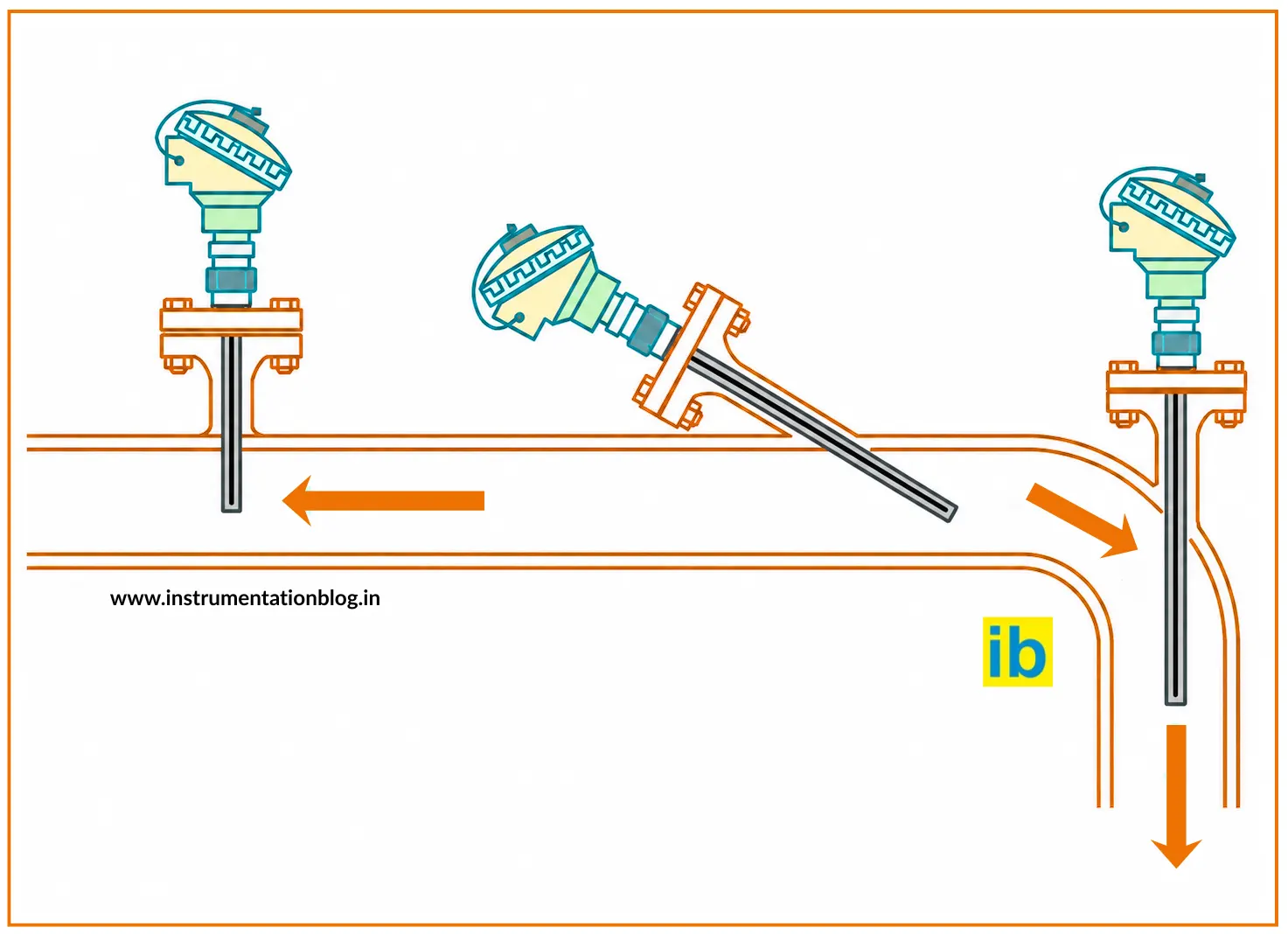
Figure 1: Three thermowell installation angles. At 90 degrees (radial), the full flow velocity acts on the thermowell creating maximum vortex shedding. At 45 degrees (angled into flow), only the component of velocity perpendicular to the thermowell acts, reducing cross-flow velocity to 0.707V and wake frequency by 29%. At 0 degrees (axial), there is no cross-flow and no vortex shedding, but this is only possible at pipe elbows or end-of-pipe entries.
The Engineering Physics: Strouhal Number and Wake Frequency
To understand why 45 degrees works, you need to understand the Strouhal number and the wake frequency formula. This is the science that ASME PTC 19.3 TW-2010 is built on, and it is what every thermo-well datasheet calculation is based on when selecting insertion length, bore diameter and installation angle.
Where:
f_w = wake frequency (vortex shedding frequency) in Hz
S = Strouhal number (dimensionless, typically 0.22 for cylinders at Re 1000-100000)
V = fluid velocity perpendicular to the thermo-well axis (m/s)
d = thermo-well outer diameter at the tip (m)
Effect of installation angle on effective cross-flow velocity: At 90° (radial): V_effective = V x sin(90°) = V x 1.000 = V (full velocity)
At 45° (angled): V_effective = V x sin(45°) = V x 0.707 = 0.707V (29% reduction)
At 30° (angled): V_effective = V x sin(30°) = V x 0.500 = 0.500V (50% reduction)
At 0° (axial): V_effective = V x sin(0°) = V x 0.000 = 0 (no cross-flow)
Wake frequency comparison (same pipe, same fluid velocity): f_w at 90°: = S x V / d (baseline)
f_w at 45°: = S x 0.707V / d = 0.707 x f_w(90°) (29% lower)
Conclusion: A 45° installation reduces the vortex shedding frequency by 29% compared to a 90° installation. This shifts the wake frequency away from the thermowell natural frequency, reducing or eliminating resonance risk. The Strouhal number is approximately 0.22 for circular cylinders (thermowell cross-sections) in the turbulent flow range (Reynolds number 1000 to 100,000) typical of process piping. ASME PTC 19.3 TW uses St = 0.22 as the standard value for thermowell wake frequency calculations.
ASME PTC 19.3 TW Thermo-well Resonance Check
The ASME PTC 19.3 TW-2010 standard requires that thermo-well installations be checked for resonance risk before commissioning. The check compares the calculated wake frequency (f_w) to the thermo-well's natural frequency (f_n). If the ratio is too close to 1.0, the thermo-well will resonate and must be redesigned or the installation angle changed.
f_w / f_n less than 0.8 (for in-line vibration, operating condition)
f_w / f_n less than 0.6 (for in-line vibration, worst-case overspeed condition)
Where:
f_w = wake frequency = S x V_effective / d
f_n = natural frequency of the thermowell (depends on geometry and material)
Simplified natural frequency formula for a thermowell (cantilevered beam): f_n = (1.875)² / (2 x pi x L²) x sqrt(E x I / (m_per_length))
Where L = insertion length (U-length), E = Young's modulus, I = second moment of area
How changing angle helps: At 90°: V_effective = 5 m/s, f_w = 0.22 x 5 / 0.022 = 50 Hz
If f_n = 55 Hz: ratio = 50/55 = 0.91 FAIL (too close to resonance)
At 45°: V_effective = 0.707 x 5 = 3.54 m/s, f_w = 0.22 x 3.54 / 0.022 = 35.4 Hz
If f_n = 55 Hz: ratio = 35.4/55 = 0.64 PASS (safe margin achieved)
Same thermowell, same pipe, same flow: the 45° angle brings the installation into the ASME PTC 19.3 TW safe zone without any change to the thermowell hardware.
Five Engineering Reasons for Thermowell 45 Degree Angle Installation
As demonstrated by the Strouhal number formula, a 45 degree installation reduces the effective cross-flow velocity to 0.707 times the pipe velocity, reducing the vortex shedding frequency by 29%. This shifts the wake frequency away from the thermowell's natural frequency, creating the safety margin required by ASME PTC 19.3 TW-2010. In small pipes (2" to 4") with high velocities (above 3 m/s for water, above 15 m/s for steam), a 90 degree thermowell frequently fails the ASME resonance check. The same thermowell at 45 degrees may pass without any hardware changes.
Thermowell fatigue failures from vortex-induced vibration are one of the most serious process safety incidents in temperature measurement: the thermowell fractures at the pipe nozzle root, allowing hot or pressurised fluid to escape. This is the primary reason thermowell selection and installation must follow ASME PTC 19.3 TW, not informal rules of thumb.
A thermowell installed at 45 degrees pointing upstream has its tip positioned more towards the pipe centreline, where the fluid velocity (and therefore the heat transfer coefficient) is highest. At 90 degrees in a small pipe, the thermowell tip may only extend 30-50% of the way across the pipe diameter, sitting in the boundary layer where fluid velocity and temperature can differ from the centreline. At 45 degrees, the same U-length places the tip closer to the true bulk fluid temperature.
Heat transfer from fluid to thermowell tip follows Newton's law of cooling. The heat transfer coefficient (h) is proportional to fluid velocity to the power 0.6-0.8 for turbulent flow. Higher velocity at the pipe centreline means faster heat transfer to the sensor, reducing thermal lag and improving response time. This directly affects the quality of temperature transmitter accuracy in dynamic processes.
This is the most immediately practical reason why technicians encounter 45 degree thermowells in the field. In a 2-inch pipe (50 mm internal diameter), the centreline is only 25 mm from the pipe wall. A standard thermowell tip diameter of 10-14 mm cannot physically achieve centreline immersion at 90 degrees without the thermowell tip touching the opposite pipe wall, which is a serious design violation.
At 45 degrees, the geometric insertion into the pipe is:
Effective radial depth = U_length x sin(45°) = U_length x 0.707
A 2.5-inch (63.5 mm) U-length thermowell at 45 degrees achieves 63.5 x 0.707 = 44.9 mm of radial immersion, enough to reach near the centreline of a 2-inch pipe without touching the far wall. The same thermowell at 90 degrees would reach beyond the pipe centreline in a 2" pipe. The 45 degree angle solves the geometric constraint that 90 degree installation creates in small pipes.
Any object inserted into a flowing fluid creates a pressure drop. For a thermowell installed at 90 degrees, the obstruction area is the thermowell diameter multiplied by its immersion length, presented full-face to the flow. At 45 degrees, the projected obstruction area in the flow direction is reduced, because only the component of the thermowell's frontal area perpendicular to flow direction contributes to pressure drop.
In high-flow or custody transfer applications where pressure integrity and flow profile accuracy matter, reducing the thermowell pressure drop is an important secondary benefit of the 45 degree installation. The reduction is not dramatic (typically 5-15% lower pressure drop) but in critical measurement runs such as fiscal gas metering where a flow meter like a venturi operates upstream or downstream, every source of flow disturbance is minimised.
A 45 degree thermowell nozzle on a horizontal pipe positions the thermowell head at an angle that is ergonomically accessible from alongside the pipe. A 90 degree installation on the top of a horizontal pipe requires the technician to work directly above the pipe, which is awkward and can be hazardous on elevated pipe racks or insulated lines. On vertical pipes, a 90 degree thermowell points horizontally into a congested pipe corridor, while a 45 degree installation angles the head downward and outward for easier access.
On heavily insulated lines (steam, hot oil, cryogenic), the insulation around a 45 degree nozzle is easier to cut and replace than a 90 degree nozzle because the nozzle penetrates the insulation at an angle that allows a cleaner cut and weatherproof seal. This reduces maintenance time and the risk of moisture ingress into the insulation.
When NOT to Use a 45 Degree Thermowell Installation
- Large bore pipes (8 inches and above): In an 8-inch pipe the centreline is 100 mm from the wall. A standard thermowell U-length of 4.5 inches (114 mm) at 45 degrees gives 114 x 0.707 = 80 mm radial immersion, still well short of centreline. At 90 degrees, the same thermowell achieves 114 mm radial immersion, easily reaching centreline. In large pipes, 90 degree installation is standard and the ASME PTC 19.3 TW resonance check typically passes because the lower fluid velocity in the larger pipe area gives a lower wake frequency.
- Very low flow velocities: When process velocity is well below 1 m/s (liquid) or 5 m/s (gas), the calculated wake frequency is far below the thermowell natural frequency even at 90 degrees. Angling adds no benefit and complicates the nozzle fabrication.
- Vertical pipe with downward flow and top entry: A 45 degree installation in this case can create a stagnant zone on the downstream (lower) side of the thermowell where sediment or condensate collects, potentially affecting accuracy or causing corrosion.
- Where structural constraints prevent angled nozzle welding: Some pipe classes (particularly in ASME B31.3 high-pressure piping) have restrictions on the angle of branch connections to pipe runs. The piping engineer must confirm the connection angle is permitted in the applicable piping class.
Standards Supporting Thermowell 45 Degree Angle Installation
| Standard | Organisation | What it covers related to thermowell angle |
|---|---|---|
| ASME PTC 19.3 TW-2010 | American Society of Mechanical Engineers | The definitive thermowell design and vibration analysis standard. Specifies the wake frequency calculation (Strouhal number method), natural frequency calculation, resonance safety criteria (f_w/f_n less than 0.8) and steady-state stress limits. Explicitly recognises that angled installations reduce effective cross-flow velocity. All thermowell datasheets must reference this standard for vibration compliance. |
| API RP 551 | American Petroleum Institute | Recommended practice for temperature measurement in refineries and processing plants. Recommends angled thermo-well installations for small bore pipes and specifies standard U-lengths (2.5", 4.5", 6.0"). States that insertion depth should place the sensor tip at or near the pipe centreline, which mandates angled installation for pipes under 4 inches. |
| IEC 60584 / IEC 61515 | International Electrotechnical Commission | IEC 60584 covers thermocouple specifications. IEC 61515 covers industrial platinum resistance thermometers. Both specify sensor accuracy classes and material requirements that interact with thermo-well design. Neither directly mandates installation angle but both require the installation to achieve the stated measurement accuracy, which implicitly requires adequate immersion and thermal contact. |
| ISA-RP12.2 | International Society of Automation | Recommended practice for electrical instruments in hazardous atmospheres. Covers safe sensor orientation and protection class requirements. Specifies that installation angle must be selected based on process conditions and mechanical limits, not convenience. |
| EIL (Engineers India Limited) Standards | Engineers India Limited | Project-specific standards widely used in Indian EPC and oil and gas projects. Specify standard U-lengths, flange ratings (150#, 300#, 600#), material grades (SS316, Monel, Hastelloy), and installation angles for specific pipe sizes. EIL standards typically mandate 45 degree installations for pipes 4 inches and below and 90 degree for pipes 6 inches and above, subject to ASME PTC 19.3 TW vibration check. |
Quick FAQs: Thermo-well 45 Degree Installation
- Thermowell Selection Guide: U-Length, Materials, Wake Frequency and ASME PTC 19.3 TW
- How to Calibrate a Temperature Transmitter: Step-by-Step Procedure
- Thermocouple Types J, K, T, E, N, S, R and B: Complete Comparison Guide
- RTD Resistance to Temperature Calculator: PT100 and PT1000 with Lead Wire Error
- Cold Junction Compensation in Thermocouples: Why It Is Needed and How It Works
External References
- ASME PTC 19.3 TW-2010: Thermowells Standard
- Emerson: Thermowell Selection and ASME PTC 19.3 TW Compliance
- AutomationForum: Why Thermowells Are Installed at 45 Degrees
What we learn today
- Thermowells are installed at 45 degrees to reduce vortex-induced vibration. The Strouhal formula f_w = 0.22 x V / d shows that wake frequency depends on cross-flow velocity. At 45 degrees, effective velocity is V x sin(45°) = 0.707V, reducing wake frequency by 29% versus 90 degrees and creating the safety margin required by ASME PTC 19.3 TW-2010 (f_w/f_n must be below 0.8).
- Three additional engineering benefits of 45 degree installation: (1) better immersion in small pipes under 4 inches where 90 degrees would overshoot or undershoot pipe centreline, (2) higher heat transfer coefficient from deeper centreline placement improving response time, (3) easier maintenance access on elevated or insulated piping.
- Use 45 degrees for pipes 4 inches and below, or any pipe where the ASME PTC 19.3 TW resonance check fails at 90 degrees. Use 90 degrees for pipes 6 inches and above where lower velocities mean the resonance check passes. Always base the decision on the ASME PTC 19.3 TW calculation, not rules of thumb.