
Instrumentation · Commissioning · Loop Check
Instrument Loop Checking: A Complete Step-by-Step Procedure
A practical field guide to loop checking: what it is, the difference between cold and hot loop checks, how to check each instrument type, what to document, and how to fix the most common problems found during commissioning.
The instruments are installed. The cables are pulled and terminated. The DCS or PLC is powered up and the SCADA screen is live. But before a single valve opens or a motor starts, every instrument loop must be verified end to end. This verification is called a loop check, and it is one of the most critical activities in the commissioning of any process plant.
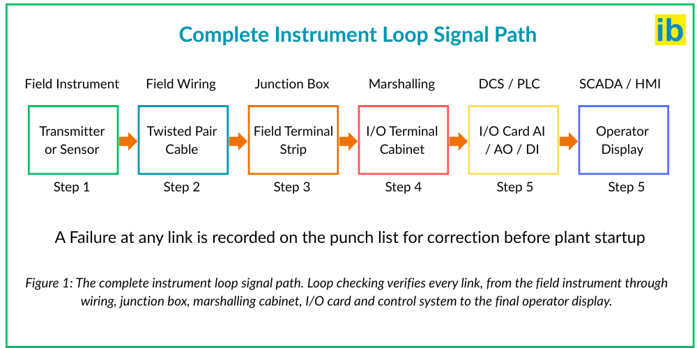
A loop check confirms that the signal travels correctly from the field instrument through the wiring, junction boxes, marshalling cabinet and I/O cards all the way to the control system display. The value the value shown on the DCS or SCADA screen is accurate, correctly scaled and properly alarmed. It catches wiring errors, configuration mistakes and calibration problems while they are still cheap to fix, before the process is live.
This guide covers the complete loop checking procedure used in oil and gas, chemical, water and power plants. It covers everything from pre-check requirements and cold loop checks through hot loop verification, documentation and sign-off. Whether you are a commissioning engineer on your first project or a technician refreshing your knowledge, this step-by-step guide gives you everything you need.
What Is Instrument Loop Checking?
A loop check is the end-to-end verification of a complete instrument signal path. It confirms that every component in the loop: the field instrument, the field wiring, the junction box, the marshalling cabinet, the I/O card and the control system configuration. Each must be correctly connected, correctly configured and correctly displaying the right value in the right engineering units.
Think of it as a complete chain test. You start at the field instrument, apply a known signal and verify it appears correctly at the other end of the chain: the DCS display, the SCADA screen, or the PLC HMI. If any link in the chain is broken, reversed, wrong or misconfigured, the loop check reveals it.
Watch: Instrument Loop Check Procedure (Video)
Before going through the detailed steps, this video gives a clear visual walkthrough of a real instrument loop check in the field:
Pre-Requisites Before Starting Loop Checks
Loop checking cannot start until certain conditions are in place. Starting too early wastes time and produces meaningless results. The following must all be confirmed before the first loop check begins:
- All instrument installation is complete. The field instrument must be physically installed in its final location, with the correct process connection, mounting, and cable gland. It must have its instrument tag plate fitted.
- All cable pulling and termination is complete. Every wire in the loop must be terminated at all points: field instrument head, junction box, marshalling cabinet and I/O card. Verify against the cable schedule and termination drawings.
- Instruments are calibrated. All transmitters must be calibrated to their specified range before loop checking. A loop check on an uncalibrated transmitter is a wasted exercise.
- DCS/PLC is powered and configured. The control system must be running with the I/O database loaded. The correct tag, range, engineering units and alarm setpoints must be configured for each loop.
- SCADA or HMI graphics are available. The operator display must be ready so the loop check team can verify what the operator will see during plant operation.
- Documentation is available. Loop diagrams, P&IDs, instrument datasheets, cable schedules and I/O lists must all be on hand for cross-referencing during the check.
- Loop check sheets are prepared. Blank loop check sheets for each loop must be ready for recording as-found results and sign-off.
- Two-person team and radio communication. Loop checking requires one person at the field instrument and one person at the control system terminal, communicating by radio. Budget 20 to 25 loops per day for a well-organised two-person team.
Cold Loop Check vs Hot Loop Check: What Is the Difference?
Loop checking is carried out in two distinct phases. Both are required before handover to operations.
Cold Loop Check (Unpowered / Continuity Phase)
- Carried out before instrument power is applied
- Verifies physical wiring continuity and correct cable landing
- Uses a multimeter or continuity tester
- Checks: polarity, continuity, cable tag, insulation resistance, no shorts to earth
- Does not verify signal values or DCS display
- Catches crossed wires, open circuits and reversed polarity
Hot Loop Check (Powered / Signal Phase)
- Carried out with instrument power applied and DCS live
- Verifies the complete signal path with simulated process signals
- Uses a loop calibrator and HART communicator
- Checks: signal at 0%, 25%, 50%, 75%, 100%; DCS display values; engineering units; alarms
- Verifies control valve response (for output loops)
- Catches scaling errors, configuration mistakes and calibration drift
| Parameter | Cold Loop Check | Hot Loop Check |
|---|---|---|
| Power status | Unpowered | Powered. Instrument and DCS live |
| Tools used | Multimeter, continuity tester, insulation tester | Loop calibrator, HART communicator, multimeter |
| What is verified | Wiring continuity, polarity, cable identification, insulation | Signal values, DCS display, engineering units, alarm setpoints, valve response |
| Typical test points | Continuity check only | 0%, 25%, 50%, 75%, 100% of range |
| Sequence | First | Second. Only after cold check is passed |
Cold Loop Check Procedure: Step by Step
- Gather documentation Collect the loop diagram, cable schedule, instrument datasheet and I/O list for the loop being checked. Confirm the instrument tag number matches the physical tag plate on the instrument and the cable tag at the junction box and marshalling cabinet.
- Visual inspection at the field instrument Physically inspect the instrument: correct model and range, correct installation orientation, correct process connection, cable gland tight, terminal cover intact. Check that the instrument tag plate matches the loop diagram. Note any punch list items.
- Verify cable identification at all termination points At the field instrument head, junction box and marshalling cabinet, confirm that the correct cable tag is terminated at the correct terminal. Cross-reference against the cable schedule. A crossed cable landing is one of the most common errors found at this stage.
- Check wiring polarity For 4-20 mA loops, confirm positive (+) and negative (-) wires are correctly identified and terminated at each end. Reversed polarity will cause no output or incorrect output when the loop is powered.
- Continuity test With the loop isolated (no power), use a multimeter or continuity tester to verify continuity from the field instrument terminals through the junction box to the marshalling cabinet terminals. There should be a clean circuit with no open connections.
- Insulation resistance test Using an insulation resistance tester (megger), test the insulation resistance between the loop conductors and earth. A value below 1 megohm indicates damaged cable insulation or moisture ingress and must be investigated before powering the loop.
- Record results and sign off Record all cold check results on the loop check sheet. Any failures become punch list items. Only loops that pass the cold check proceed to the hot loop check phase.
Hot Loop Check Procedure: Step by Step
The hot loop check is carried out with the instrument powered and the DCS or PLC running. The field technician applies simulated signals using a loop calibrator or HART communicator. The console engineer monitors and records what appears on the DCS display.
- Power up the loop and verify instrument health Apply 24V DC to the transmitter. Confirm the instrument powers up. Check for any fault indicator lights or error codes. Using the HART communicator, verify the tag number, configured range (LRV and URV), engineering units and sensor type all match the instrument datasheet and loop diagram.
- Check the DCS reads a live signal at 0% With the instrument in its normal condition (process disconnected or at zero), confirm the DCS reads approximately 0% (4.000 mA). The console engineer confirms the correct tag appears on the correct screen graphic in the correct engineering units. If the DCS shows 0.0 mA or an error, investigate before proceeding.
- Verify correct I/O channel assignment The console engineer confirms in the I/O database that this tag is mapped to the correct I/O card and channel number. A signal appearing on the wrong tag or wrong channel is a wiring error that must be corrected before continuing.
- Apply 25% signal and record DCS reading The field technician uses the HART communicator or loop calibrator to simulate 25% of the measurement range (8.000 mA for a 4-20 mA loop). The console engineer reads the value shown on the DCS and records it. The DCS should display 25% of the configured engineering unit span. For example, for a 0 to 10 bar transmitter, the display should show 2.5 bar.
- Apply 50% and 75% signals Repeat the same process at 50% (12.000 mA) and 75% (16.000 mA). At each point, the console engineer records the expected and actual DCS readings. A linear relationship between the injected percentage and the displayed value confirms correct scaling in the DCS configuration.
- Apply 100% signal and verify span Apply 100% (20.000 mA). The DCS should read the Upper Range Value in the correct engineering units. For the 0 to 10 bar example, the display should show 10.0 bar. Any discrepancy at the high end indicates a span error in the DCS scaling configuration.
- Verify alarm setpoints Using the HART communicator, simulate the value above and below each alarm setpoint in sequence. Confirm each alarm appears on the DCS at the correct value and with the correct priority (Low, High, Low-Low, High-High). Confirm the alarm text description is correct and matches the alarm cause. Test the alarm return to normal condition as well.
- Test NAMUR fault detection (open circuit and short circuit) For smart transmitters with NAMUR NE43 compliance, verify the fault detection by disconnecting one wire at the field end and confirming the DCS shows a fault or error alarm (typically below 3.6 mA for a broken wire). Reconnect and verify the loop returns to normal. See our guide on NAMUR NE43 signal range and fault detection for more detail.
- Repeat upscale and downscale Repeat the 5-point check in reverse order (100% down to 0%) to check for any hysteresis or signal inconsistency. Record all readings.
- Record as-found results and sign off Record all five test point readings (expected vs actual) on the loop check sheet. Note any deviations. The loop passes if all readings are within the acceptable tolerance (typically within 1% of span for process loops). Any failure becomes a punch list item for correction and re-test. Both the field technician and the console engineer sign the loop check sheet.
Loop Check Procedure by Instrument Type
Transmitters (Pressure, Level, Flow, Temperature)
For transmitters, the standard hot loop check uses a HART communicator to simulate the output signal at 0%, 25%, 50%, 75% and 100% of the configured range directly from the transmitter terminals. The HART communicator connects to the loop in parallel and issues a fixed-output command to the transmitter. No physical process simulation is needed for the signal path check. For temperature transmitters, verify cold junction compensation settings and sensor type configuration as part of the check. See our detailed guides on temperature transmitter calibration and differential pressure transmitter calibration.
Switches (Pressure Switch, Level Switch, Temperature Switch)
For on/off switches, the loop check verifies that the discrete input signal changes state at the control system when the switch operates. The field technician actuates the switch (by applying pressure, a magnet or temperature as appropriate, or by using the test button if available). The console engineer confirms the digital input changes from 0 to 1 (or 1 to 0 for normally closed switches) at the correct I/O channel in the DCS. Alarm generation and any interlock or trip function are also verified during the switch loop check.
Control Valves (Analog Output Loop)
For control valve output loops, the check is reversed: the console engineer sends a signal from the DCS output and the field technician observes the valve response. The DCS analog output is driven to 0%, 25%, 50%, 75% and 100% in sequence. The field technician confirms the valve stem or position indicator moves to the corresponding position. The valve is also checked for correct fail-safe action by removing the instrument air: confirm the valve goes to its correct fail-open or fail-closed position and that the DCS sees the valve position feedback (if fitted) correctly.
Gas Detectors and Analyser Loops
Gas detectors are loop-checked by applying certified test gas from a calibration cylinder to the sensor head. The concentration of the test gas is known and the DCS value should correspond correctly. Never inject simulated mA signals into a gas detector to perform a loop check. Always use actual test gas to verify the entire detection chain. For analyser loops, consult the vendor commissioning procedure as the loop check method varies by technology type.
| Instrument type | Signal type | Loop check method | Test tool |
|---|---|---|---|
| Pressure transmitter | 4-20 mA analogue | HART simulate output or loop calibrator inject | HART communicator or loop calibrator |
| Temperature transmitter | 4-20 mA analogue | HART simulate output. Check CJC, sensor type. | HART communicator |
| Flow transmitter (DP) | 4-20 mA analogue | HART simulate output. Check square root extraction. | HART communicator |
| Level transmitter | 4-20 mA analogue | HART simulate output. Check density setting. | HART communicator |
| Pressure switch | Digital (DI) | Actuate switch, verify DCS digital input changes state | Test pump or manual actuation |
| Control valve | 4-20 mA output (AO) | Drive DCS output 0-25-50-75-100%. Check valve travel. | DCS operator station |
| Gas detector | 4-20 mA analogue | Apply certified test gas to sensor head | Certified test gas cylinder |
| Vibration monitor | Analogue or discrete | Check cable polarity and continuity. Apply test signal from proximitor test point. | Oscilloscope or calibration tool |
Loop Check Sheet Template
Every loop must have a signed loop check sheet on completion. This sheet is the legal record of the check and is required for handover to operations, regulatory compliance and any future audit or incident investigation. The sheet below shows the standard format used on most projects:
| INSTRUMENT LOOP CHECK SHEET | |||||||
|---|---|---|---|---|---|---|---|
| Tag Number | Description | I/O Address | Range | Test Point | Expected (mA / %) | Actual (DCS) | Pass / Fail |
| PT-1001 | Reactor Inlet Pressure | AI-04-01 | 0-10 bar | 0% (LRV) | 4.000 mA / 0.0 bar | ______ | ______ |
| 25% | 8.000 mA / 2.5 bar | ______ | ______ | ||||
| 50% (Mid) | 12.000 mA / 5.0 bar | ______ | ______ | ||||
| 75% | 16.000 mA / 7.5 bar | ______ | ______ | ||||
| 100% (URV) | 20.000 mA / 10.0 bar | ______ | ______ | ||||
| Alarm check: LL = ___ L = ___ H = ___ HH = ___ | Fault detection test | ______ | |||||
| Sign-off field | Name | Signature | Date |
|---|---|---|---|
| Field technician | __________ | __________ | __________ |
| Console engineer | __________ | __________ | __________ |
| Commissioning supervisor | __________ | __________ | __________ |
Common Loop Check Problems and How to Fix Them
| Problem found | Likely cause | Corrective action |
|---|---|---|
| No signal at DCS: loop reads 0 mA or error | No loop power. Open circuit in wiring. Cable landed on wrong terminal. Blown fuse on I/O card power supply. | Check 24V supply at transmitter terminals. Test continuity from field to marshalling cabinet. Verify cable tag against cable schedule. Check I/O card fuse. |
| DCS reads correct mA but wrong engineering value (e.g. shows 12 mA but displays wrong bar value) | Incorrect LRV or URV configured in DCS I/O database. Wrong engineering units entered. Wrong instrument range assumed during configuration. | Check DCS AI configuration for that tag. Correct the LRV, URV and engineering units to match the instrument datasheet. |
| Signal appears on wrong tag or wrong DCS screen | Cable terminated at the wrong marshalling terminal. I/O address mapped to wrong tag in DCS database. | Trace the cable from field to marshalling cabinet. Correct the termination. Verify I/O address in DCS configuration database. |
| Signal is reversed (4 mA shows 100%, 20 mA shows 0%) | Positive and negative wires are reversed somewhere in the loop. DCS configured for inverted transfer function. | Check wiring polarity at each termination point. Swap positive and negative at the most accessible termination point. Alternatively correct the transfer function in DCS if inversion is intentional (e.g. fail-safe level). |
| Alarm does not trigger at correct value | Wrong alarm setpoint entered in DCS. Alarm in wrong engineering units (e.g. % instead of bar). Alarm disabled or in bypass status. | Check alarm setpoint values in DCS configuration against the approved instrument datasheet or alarm setpoint list. Confirm alarm is enabled and not bypassed. |
| DCS reading is correct but instrument local display shows different value | Instrument local display configured to show different units (e.g. kPa vs bar). Local display not yet configured. Output trim offset in transmitter. | Check transmitter display configuration via HART. Ensure local display is configured for the same units as the DCS. Check output trim settings. |
| HART communicator cannot communicate | Less than 250 ohms in the loop. Wrong poll address. No loop power. | Verify 250 ohm minimum resistance. Check 24V supply. Try polling all addresses. See our guide on HART protocol and HART communicator use. |
Punch List Management During Loop Checking
Every loop check deficiency that cannot be corrected immediately is recorded on a punch list. The punch list is a numbered list of outstanding items, each with a description of the fault, the loop or tag number affected, the responsible party for correction, and a target completion date.
Punch list items are categorised by priority:
- Category A (Safety critical): Must be resolved before plant startup. Includes any SIS or ESD loop failures, incorrect fail-safe valve positions, missing IS barriers.
- Category B (Operationally significant): Must be resolved before plant startup but does not affect safety directly. Includes incorrect scaling, wrong alarm setpoints, wrong tag descriptions.
- Category C (Minor): Can be resolved after startup without impact on safety or production. Includes cosmetic issues, label corrections, minor documentation updates.
No plant startup should proceed with any outstanding Category A punch list items. Category B items require written acceptance from the operations and safety team before startup permission is granted.
Further Reading and External Resources
- Divize Industrial Automation: Loop Checking Procedure. A practical, detailed loop checking guide from an industrial automation specialist including the 4-20 mA simulation method step by step.
- NFM Consulting: Instrument Loop Checks and Commissioning Procedures. Concise field-level guide covering what a loop check verifies, typical timing and team structure from a professional commissioning company.
- Inst Tools: What Is Loop Checking?. Comprehensive reference covering the loop check definition, scope and procedure for all instrument types used in industrial plants.
- Fluke: Loop Calibrators for Process Control. Technical guidance on using loop calibrators for commissioning and maintenance from the leading calibration instrument manufacturer.
Frequently Asked Questions: Instrument Loop Checking
- How to Calibrate a Temperature Transmitter: Step-by-Step Procedure
- How to Calibrate a Differential Pressure Transmitter
- HART Protocol: How It Works and How to Use a HART Communicator
- NAMUR NE43 Standard: Signal Range and Fault Detection Explained
- Signals in Instrumentation: AI, AO, DI, DO Explained
- How to Read a P&ID Diagram: Complete Guide
- What Is a PLC and How Does It Work?
- What Is a Temperature Transmitter and How Does It Work?
What we learn today
- Loop checking is the end-to-end verification of the complete signal path from field instrument through wiring, junction box, marshalling cabinet and I/O card to the DCS or SCADA display.
- Calibration always comes before loop checking. Calibration adjusts the instrument. Loop checking verifies the signal path from that calibrated instrument to the control system.
- There are two phases: cold loop check (continuity, polarity and insulation (no power)) and hot loop check (signal simulation at five test points, with power). Cold always comes first.
- A standard hot loop check tests at 0%, 25%, 50%, 75% and 100% of the calibrated range and verifies the DCS reading, engineering units and alarm setpoints at each point.
- For smart HART transmitters, the HART communicator simulates the output signal during the check. For non-HART instruments, a loop calibrator injects a known 4-20 mA signal directly into the loop.
- A two-person team (field technician and console engineer) communicating by radio is the standard approach. Budget 20 to 25 analogue loops per day for a well-organised team.
- Every loop check must be documented on a signed loop check sheet with expected vs actual readings at all five test points, alarm check results and fault detection verification.
- All deficiencies found become punch list items. No plant should start with outstanding Category A (safety critical) punch items unresolved.
- The most common error found during loop checking is a signal appearing on the wrong tag or wrong DCS channel. This is caused by crossed cable terminations at the marshalling cabinet.

