
Table of Contents
ToggleWhen you study instrumentation and flow measurement, one of the first and most widely used devices you will see is the orifice plate.
It may look simple, a thin metal plate with a hole, but its working principle, reliability, and cost-effectiveness make it a backbone of flow measurement in industries worldwide.
Whether it is steam flowing through a boiler line, water supply in a treatment plant, or natural gas in a pipeline ,orifice plates are everywhere.
In this article you will learn: what an orifice plate is, how it works, the main types, where and how it’s used, and its pros and cons. Great for beginners, students, and engineers alike.
What Is an Orifice Plate?
An orifice plate is a flat metal plate with a precisely drilled circular hole (called an orifice) and this plate is installed perpendicular to the flow direction inside a pipeline.
As fluid (liquid, gas, or steam) passes through the pipe and encounters the orifice, the flow is restricted causing changes in pressure and velocity.
By measuring these pressure changes, we can calculate how much fluid is flowing.
In essence:
1) Upstream of the orifice: fluid pressure is higher.
2) At the orifice: fluid velocity increases, pressure decreases (the narrow opening forces the fluid to speed up).
3) Downstream: pressure recovers partially, but not to original level — a permanent pressure loss is incurred.
Because this principle is simple and based on fundamental fluid dynamics, orifice plates are widely used for measuring flow in many industrial pipelines.
How Does Orifice Plate Work? (Working Principle)
The working of an orifice plate is based on basic fluid mechanics especially the concept that when a fluid speed goes up, its pressure goes down (Bernoulli’s principle), combined with continuity of flow.
Step-by-Step Flow Process
The fluid enters the pipe at normal cross-section. Pressure upstream (before the plate) is “p1”.
The fluid reaches the orifice, it must squeeze through the hole, so the flow area reduces.
Because area reduces, velocity increases. As velocity increases, static pressure drops pressure at the orifice throat becomes “p2”.
After passing the orifice, the fluid expands and slows down; pressure recovers partially downstream.
The difference in pressure (ΔP = p1 – p2) is measured via pressure taps upstream and downstream.
Using that ΔP and known fluid properties, we calculate the flow rate (volume flow or mass flow) through standard equations.
Mathematically, for incompressible fluids (e.g. water), a simplified relation is:

A discharge coefficient (C) is used to account for non-ideal effects (viscosity, turbulence, geometry, etc.).
Construction of Orifice Plate
Inlet Section
The inlet section is a straight pipe portion having the same diameter as the incoming pipeline. This section allows the fluid, steam, or gas to enter the orifice meter smoothly. The upstream (inlet) pressure of the flowing media is measured at this location.
Orifice Plate
The orifice plate is mounted between the inlet and outlet sections. It creates a controlled restriction in the flow path. As the fluid passes through the orifice opening, a pressure drop is generated, which is later used to calculate the flow rate.

Outlet Section
The outlet section is also a straight pipe of the same diameter as the discharge pipeline. It carries the fluid away after it passes through the orifice plate. The downstream (outlet) pressure of the media is measured in this section.
Gasket Arrangement
As shown in the diagram, gaskets are placed between the orifice plate and the flange faces. These gaskets ensure proper sealing and prevent any leakage from the flange joint.
Pressure Tapping Points
Both Section-1 (inlet) and Section-2 (outlet) are equipped with pressure tapping openings. These tapping points are used to connect a differential pressure measuring device, such as a U-tube manometer or a differential pressure transmitter, for accurate flow measurement.
Different Types of Orifice Plate
Orifice plates used in orifice meters are generally manufactured from stainless steel (SS) in different grades. The exact grade is selected based on temperature, pressure, corrosion resistance, and process conditions.
Orifice meters are designed in different forms depending on the application requirement. The shape, size, and position of the hole on the orifice plate determine its type and usage. The main types are:
1) Concentric Orifice Plate
2) Eccentric Orifice Plate
3) Segmental Orifice Plate
4) Quadrant Edge Orifice Plate
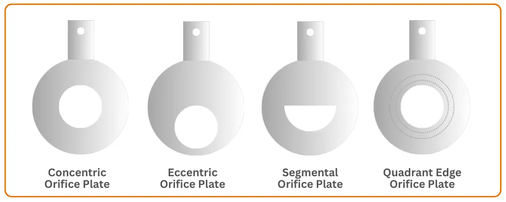
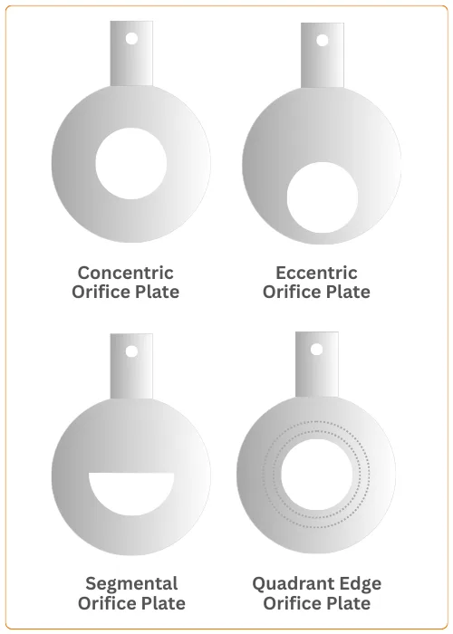
A) Concentric Orifice Plate
This is the most commonly used type of orifice-plate. It is made from stainless steel, and the plate thickness typically ranges from 3.175 mm to 12.70 mm.
To maintain proper flow measurement accuracy, the thickness at the orifice edge should not exceed any of the following limits:
- D/50, where D = Inside diameter of the pipe
- d/8, where d = Orifice bore diameter
- (D – d)/8
Beta Ratio (β)
The beta ratio (β) is defined as the ratio of the orifice bore diameter (d) to the pipe inside diameter (D).
β=d/Dβ
This ratio is very important in flow accuracy and pressure loss.
B) Eccentric Orifice Plate
The eccentric orifice-plate is similar to the concentric type, except that the hole is displaced from the center and bored tangentially to a circle concentric with the pipe. The hole diameter is usually about 98% of the pipe diameter.
This type is mainly used for flows containing:
- Fluids with solid particles
- Oils mixed with water
- Wet steam
Its offset hole prevents sedimentation and buildup of solids near the orifice opening.
C) Segmental Orifice Plate
In a segmental orifice-plate, the opening is in the form of a semi-circle or a circular segment rather than a full circular hole. The opening diameter is generally about 98% of the pipe diameter.
This type is suitable for:
- Slurries
- Dirty liquids
- Fluids with suspended solids
It allows solid particles to pass without settling inside the plate.
D) Quadrant Edge Orifice Plate
This type of orifice-plate has a rounded (quadrant-shaped) inlet edge instead of a sharp edge. It is commonly used for high-viscosity fluids, such as:
- Crude oil
- Heavy syrups
- Slurries
- Viscous chemical liquids
It is normally applied when the Reynolds number is either above 100,000 or lies between 3,000 to 5,000, and it can achieve an accuracy of approximately ±0.5% under proper conditions.
You can read our article: What is Reynolds Number
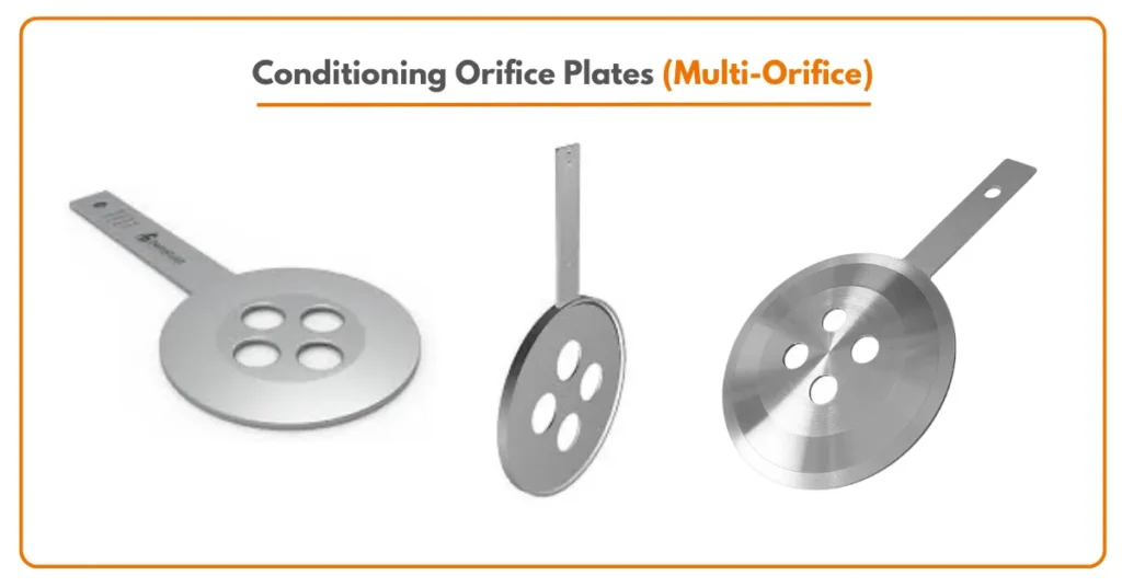
E) Conditioning Orifice Plates (Multi-Orifice)
A conditioning orifice plate, also known as a multi-orifice plate, is an advanced form of the traditional orifice plate. Instead of a single central hole, this plate contains multiple small holes arranged in a specific pattern.
These holes help in straightening and stabilizing the flow profile before it reaches the measuring section. Because of this built-in flow conditioning effect, multi-orifice plates can be installed even where long straight pipe lengths are not available, such as after elbows, control valves, or reducers.
Compared to conventional single-hole orifice plates, conditioning orifice plates offer better measurement stability, improved repeatability, and reduced sensitivity to upstream disturbances.
They also produce lower permanent pressure loss and help in achieving faster flow profile recovery. These plates are commonly used in compact skid systems, offshore platforms, packaged units, and space-restricted piping installations.
Although their initial cost is slightly higher, they reduce installation complexity and improve overall measurement performance, making them a modern and efficient alternative to traditional orifice plates.
Applications of Orifice-Plates
Orifice plates are used all over industry because of their simplicity and versatility. Here are common applications:
1) Water & wastewater treatment
2) Steam lines
3) Natural gas pipelines
4) Chemical & petrochemical plants
5) Compressed air / gas systems
6) Slurries, sludges
Because orifice plates don’t have moving parts, they can be used even in harsh environments, high temperature or high pressure systems, making them widely popular in heavy industries.
Advantages of Orifice-Plates
Orifice plates come with several strong advantages which explains why they remain so popular even after decades. Some of them:
1) Low Initial Cost & Simple Design: compared to many other types of flow meters, orifice plates are inexpensive and easy to manufacture.
2) No Moving Parts: meaning less maintenance, higher mechanical reliability.
3) Versatile: Can Measure Liquids, Gases, Steam as long as the fluid is single-phase and flow conditions are met.
4) Suitable for Many Fluid Types: clean fluids, dirty fluids, slurries (with right plate type), and various pressures/temperatures.
5) Standardization & Wide Industry Acceptance: because of ISO 5167 and other standards, results are repeatable and accepted globally.
Orifice plates give a good balance of cost, simplicity, and acceptable accuracy for many industrial applications.
Disadvantages & Limitations
Despite their popularity, orifice plates are not perfect. It is important to know where they may fail or become less suitable.
1) Permanent Pressure Loss: When fluid passes through the orifice, significant pressure drop occurs; much of the energy is lost (not recovered).
2) Limited Rangeability (Turndown Ratio): Because flow is proportional to the square root of pressure drop, small flows produce very small differential pressures, limiting measurement at low flow rates. Typical turndown is around 4:1 to 5:1.
3) Accuracy Depends on Installation & Fluid Conditions: For good accuracy you need correct straight-pipe runs upstream/downstream, proper tapping positions, stable single-phase flow, no entrained gas or solids, stable fluid properties.
4) Erosion, Wear, & Maintenance: In dirty fluids, slurries, or steam (especially wet steam), the sharp edge of the orifice can erode ⇒ discharge coefficient changes ⇒ measurement error increases.
5) Not Ideal for Multi-phase Flows or Pulsating Flow: Orifice plates assume single-phase, steady, and full-pipe flow; in multi-phase (gas + liquid) or pulsating flows, readings become inaccurate.
Thus, while orifice plates are excellent for many everyday applications, they may not be the best choice in all cases.
What we learn today?
The orifice plate is a deceptively simple yet powerful tool in the field of flow measurement. For students and engineers working with pipelines, steam, water, gas, or process fluids, understanding how an orifice plate works, its limitations, and its installation / maintenance needs is fundamental.
Because of its low cost, robust design, standardization (like ISO 5167), and versatility across fluids, orifice-based flow meters will remain a staple in industries for decades. As you advance in instrumentation, you may explore more “high-tech” flow meters but orifice plates will still be the dependable baseline.
Frequently Asked Questions (FAQ)
Q: Can orifice plates measure steam or gas?
A: Yes — orifice-plates can measure steam and gases, provided the flow is single-phase, stable, and full-pipe. For compressible fluids (gas/steam), corrections (expansion factor, density, compressibility) must be applied.
Q: What is the typical accuracy of orifice plate flow meters?
A: For well-designed and well-installed orifice meters, accuracy typically lies around ±1% to ±3% of reading (depending on conditions).
Q: Why do orifice meters have limited rangeability (turndown)?
A: Because flow rate is proportional to the square root of differential pressure, small flow changes produce even smaller ΔP making low-flow measurement inaccurate and noisy. Typical turndown is about 4:1 or 5:1.
Q: What types of orifice plates are used for dirty fluids or slurries?
A: Eccentric or segmental (wedge or slotted) orifice plates because they allow solids / particles to pass without settling or clogging, while still enabling differential pressure flow measurement.
Q: Is there significant pressure loss across an orifice plate?
A: Yes. Because of the area restriction and abrupt contraction, orifice plates cause permanent pressure drop (head loss), which is a tradeoff of the design.
4 Comments